Panasonic is considered a top manufacturer and distributor all around the world. Offering customers everything from air conditioners, entertainment systems, refrigerators, TVs and so much more for home and commercial use. Founded more than 105 years ago, Panasonic is a Japanese multinational corporation that started its operations by producing light bulb sockets. It’s easy to assume that the company has come a long way and made its place as one of the largest companies in the world.
Along with that, the company offers a wide range of top-of-the-line choices that are designed to fit your residential and commercial space. Offering you the ease of mind you need to focus on your work rather than worry about the basic workings of your home.
Regardless of how high a company is ranked, or how well the appliance is reviewed, you are at the risk of an error. An error is not here to tell you it’s time to switch out your appliance, it’s a direct signal from the device – one that tells the owner something is wrong with the system that needs to be fixed. So rather than ignoring the error codes, your appliance is showing its time to note down the Panasonic air conditioner error code and get to the bottom of the problem. To help you out we have listed down the most common error codes of Panasonic air conditioners
Inverter Split Type Codes
| Error Codes | Cause |
|---|---|
| S01 | Room temperature sensor failure |
| S02 | Indoor coil sensor failure |
| S03 | Humidity sensor failure |
| S04 | Comp. temperature sensor failure |
| S05 | Outdoor coil sensor failure |
| S06 | Outdoor air sensor failure |
| S07 | Outdoor current sensor failure |
| E01 | Indoor/outdoor communication failure |
| E02 | HIC circuit failure (Compressor/Fan circuit) |
| E03 | Outdoor unit OTP rom failure |
| E04 | Peak current cut off |
| E05 | PAM or Active circuit failure |
| E06 | High compressor discharge temperature |
| E07 | Indoor fan operating failure |
| E08 | Way valve switching failure (RV) |
| E09 | No refrigerant protection |
| E10 | DC compressor drive circuit failure |
| E11 | Outdoor fan operating failure |
| E12 | Error in outdoor unit |
| E13 | Freeze prevention activated |
Remote Control Display Meaning

Multi AC Codes
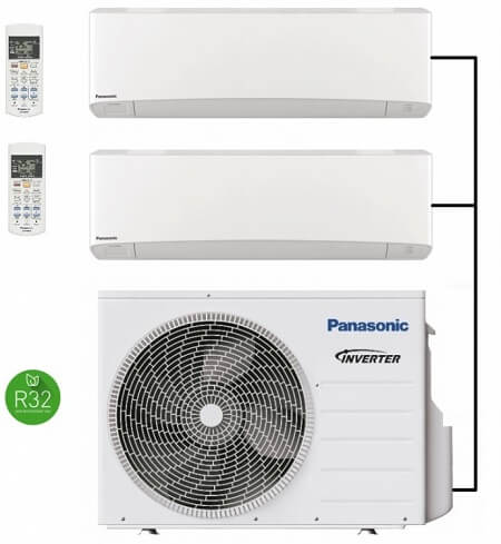
| Error Codes | Problem |
|---|---|
| H00 | No abnormality detected |
| H11 | Indoor-outdoor abnormal communication |
| H14 | Indoor intake air temperature sensor abnormality |
| H15 | Outdoor compressor temperature sensor abnormality |
| H16 | Outdoor Current Transformer open circuit |
| H19 | Indoor fan motor merchanism lock |
| H23 | Indoor heat exchanger temperature sensor abnormality |
| H24 | Indoor heat exchanger temperature sensor 2 abnormality |
| H27 | Outdoor air temperature sensor abnormality |
| H28 | Outdoor heat exchanger temperature sensor abnormality |
| H30 | Outdoor discharge air temperature sensor abnormality |
| H33 | Indoor/Outdoor wrong connection |
| H38 | Indoor/outdoor mismatch (brand code) |
| H97 | Outdoor fan motor mechanism locked |
| H98 | Indoor high pressure protection |
| H99 | Indoor heat exchanger anti-freezing protection |
| F11 | Cooling/Heating cycle changeover abnormality |
| F90 | PFC control |
| F91 | Refrigeration cycle abnormal |
| F93 | Outdoor compressor abnormal revolution |
| F95 | Cool high pressure protection |
| F96 | IPM (power transistor) overheating protection |
| F97 | Outdoor compressor overheating protection |
| F98 | Total running current protection |
| F99 | Outdoor Direct Current (DC) peak detection |
Cassette AC Codes
If the problem persists even after you check the foregoing items, stop the unit, disconnect the power to the indoor unit and contact the dealer where the product was purchased with the model number and problem you are having.
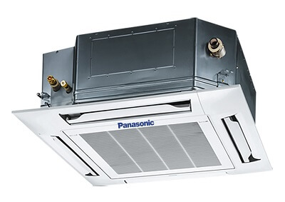
| Error Codes | Problem |
|---|---|
| E06 | Outdoor unit failed to receive serial communication signals from indoor unit |
| E07 | Outdoor unit sending failure to indoor unit |
| E12 | Automatic address setting start is prohibited while auto-address setting in progress. |
| E14 | Main unit duplication in simultaneous-operation multi control (detected outdoor unit) |
| E15 | Automatic address alarm (capacity too low) |
| E16 | Automatic address alarm (capacity too high) |
| E20 | No indoor units connected |
| F04 | Compressor discharge temperature sensor (TD) trouble |
| F06 | Inlet temperature sensor (C1) in heat exchanger trouble |
| F07 | Intermediate temperature (C2) in heat exchanger trouble |
| F08 | Outdoor air temperature sensor (TO) trouble |
| F12 | Compressor inlet suction temperature sensor (TS) trouble |
| F31 | Outdoor unit nonvolatile memory (EEPROM) trouble |
| H01 | Primary (input) overcurrent detected |
| H02 | PAM trouble |
| H03 | Primary current CT sensor (current sensor) failure |
| H05 | Sensor failure, Compressor discharge temperature sensor (TD) disconnected |
| H31 | HIC trouble |
| L04 | Outdoor unit address duplication |
| L10 | Outdoor unit capacity not set |
| L13 | Indoor unit type setting error |
| L18 | 4-way valve operation failure |
| P03 | Compressor discharge temperature trouble |
| P04 | High pressure trouble |
| P05 | AC power supply trouble |
| P13 | Alarm valve open |
| P14 | O2 sensor detect |
| P15 | Insufficient gas level detected |
| P16 | Compressor overcurrent trouble |
| P22 | Outdoor unit fan motor trouble |
| P29 | Lack of INV compressor wiring, INV compressor actuation failure (including locked) due to DCCT failure |
VRF AC Codes
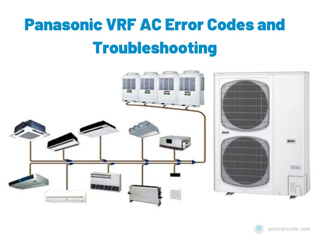
Indoor unit is detecting error signal from remote controller (and system controller).
| Error Codes | Meaning |
|---|---|
| E01 | Error in receiving serial communication signal. |
| E02 | Error in transmitting serial communication signal. |
| E03 | Indoor unit is detecting error signal from remote controller. |
| E04 | Error in receiving serial communication signal. When turning on the power supply, the number of connected indoor units does not correspond to the number set. |
| E06 | Error of the outdoor unit in receiving serial communication signal from the indoor unit. |
| E08 | Indoor unit address setting is duplicated. |
| E09 | Remote controller address connector. |
| E12 | Starting auto address setting is prohibited. This alarm message shows that the auto address connector CN-A.ADD is shorted while other RC line is executing auto address operation. |
| E15 | Error in auto address setting. |
| E16 | Error in auto address setting. |
| E20 | No indoor unit is connected during auto address setting. |
| E24 | Main outdoor unit is detecting error signal from sub outdoor unit. |
| E25 | Error of outdoor unit address setting. |
| E26 | The number of connected main and sub outdoor units do not correspond to the number set at main outdoor unit PCB. |
| E29 | Error of sub outdoor unit in receiving serial communication signal from main outdoor unit. |
| E30 | Transmission from outdoor unit faulty. |
| E18 | Error of main indoor unit in receiving serial communication signal from sub indoor units. |
| L02 | This alarm message shows when the indoor unit for multiple-use is not connected to the outdoor unit. |
| L03 | Duplication of main indoor unit address setting in group control. |
| L04 | Duplication of outdoor R.C. address setting. |
| L05 | Priority set remote controller. |
| L06 | Non-priority set remote controller. |
| L07 | Group control wiring is connected to individual control indoor unit. |
| L08 | Indoor unit address is not set. |
| L09 | Capacity code of indoor unit is not set. |
| L10 | Capacity code of outdoor unit is not set. |
| L18 | 4-way valve operation failure. |
| P01 | Thermal protector in indoor unit fan motor is activated. |
| P09 | Improper wiring connections of ceiling panel. |
| P10 | Float switch is activated. |
| P12 | Operation of protective function of fan inverter |
| P03 | Incorrect discharge temperature. (Comp. No. 1) |
| P04 | The internal circuit of the high pressure switch is dead |
| P05 | Power supply circuit failure, missing-phase detection. |
| P13 | There is a trouble with the outdoor unit when the liquid valve and the gas valve are closed. |
| P14 | O2 sensor (detects low oxygen level) activated |
| P16 | Compressor running failure resulting from missing phase in the compressor wiring, etc. |
| P22 | Outdoor unit fan motor is unusual. |
| H31 | IPM trip (IPM current or temperature) |
| P29 | Missing-phase/reverse-phase in the compressor wiring, Compressor start-up failure |
| F01 | Indoor coil temp. sensor (E1) |
| F03 | Indoor coil temp. sensor (E3) |
| F10 | Indoor suction air (room) temp. sensor (TA) |
| F11 | Indoor discharge air temp. sensor (BL) |
| F04 | Compressor No. 1 discharge gas temp. sensor (TD) |
| F07 | Outdoor No. 1 coil liquid temp. sensor (C1) |
| F08 | Outdoor air temp. sensor (TO) |
| F12 | Compressor intake port temperature sensor (TS) |
| F16 | High pressure sensor failure |
| F29 | EEPROM on indoor unit PCB failure |
| F31 | EEPROM on the outdoor unit PCB is a failure. |
| H01 | Overcurrent of power supply current (CT) sensor |
| H02 | PAM failure |
| H03 | Power supply current (CT) sensor failure |
| C05 | Indoor or main outdoor unit is not operating correctly. Mis-wiring of control wiring between indoor unil, main outdoor unit and system controller. |
| C06 | Indoor or main outdoor unit is not operating correctly. Mis-wiring of control wiring between indoor unit, main outdoor unit and system controller. CN1 is not connected properly. |
| P30 | When using wireless remote controller or system controller, in order to check the alarm message in detail, connect wired remote controller to indoor unit temporarily. |
Troubleshooting
The following symptoms do not indicate malfunction;
| Symptom | Cause |
|---|---|
| Mist emerges from indoor unit. | Condensation effect due to cooling process |
| Water flowing sound during operation. | Refrigerant flow inside the unit. |
| The room has a peculiar odour | This may be due to damp smell emitted by the wall, carpet, furniture or clothing |
| Indoor fan stops occasionally during automatic fan speed setting | This helps to remove the surrounding odour |
| Airflow continues even after operation has stopped | Extraction of remaining heat from the indoor unit (maximum 30 seconds) |
| Operation is delayed a few minutes after restarting | The delay is a protection to the unit’s compressor |
| Outdoor unit emits water/steam | Condensation or evaporation occurs on pipes |
| POWER indicator blinks during HEAT mode with no warm air supply (and louver is closed) | The unit is in defrost mode (and AIR SWING is set to AUTO) |
| Indoor fan stops occasionally during heating operation | To avoid unintended cooling effect |
| POWER indicator blinks before the unit is switched on | This is a preliminary step in preparation for the operation when the ON timer has been set |
| Cracking sound during operation | Changes of temperature caused the expansion/contraction of the unit |
| POWER indicator blinks 3 seconds ON and 0.5 seconds OFF during operation | Cause: The unit is in Demand Response Mode. Check: the following before calling for servicing |
| Noisy during operation | Check: Check if the unit has been installed at an incline. Close the front panel properly. |
| Remote control does not work | Check: Insert the batteries correctly. Replace weak batteries. |
| The unit does not work | Check: Check if the circuit breaker is tripped. Check if timers have been set. |
| The unit does not receive the signal from the remote control. | Check: Make sure the receiver is not obstructed. Certain fluorescent lights may interfere with signal transmitter. Please consult authorised dealer. |
Wiring Diagram
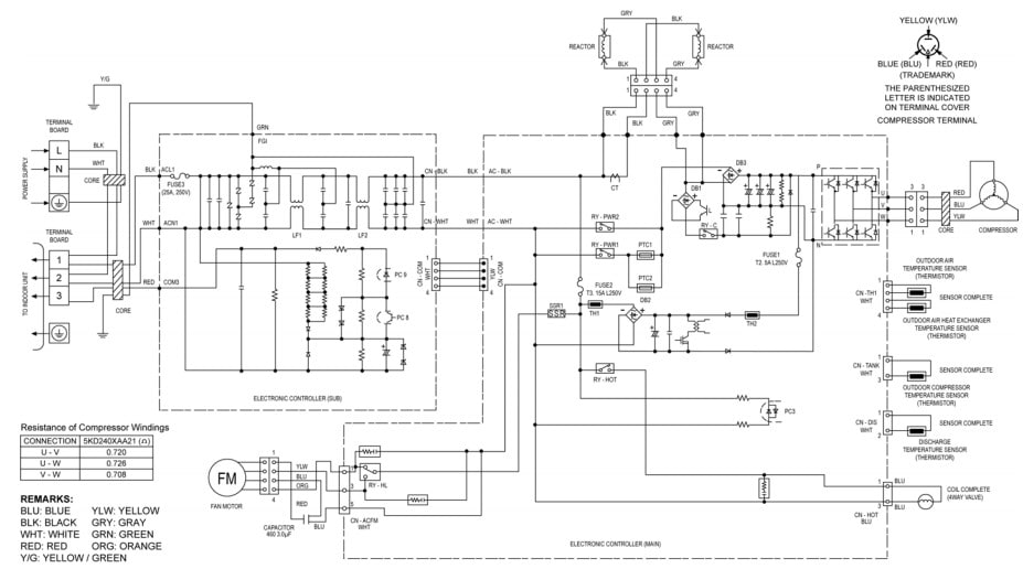
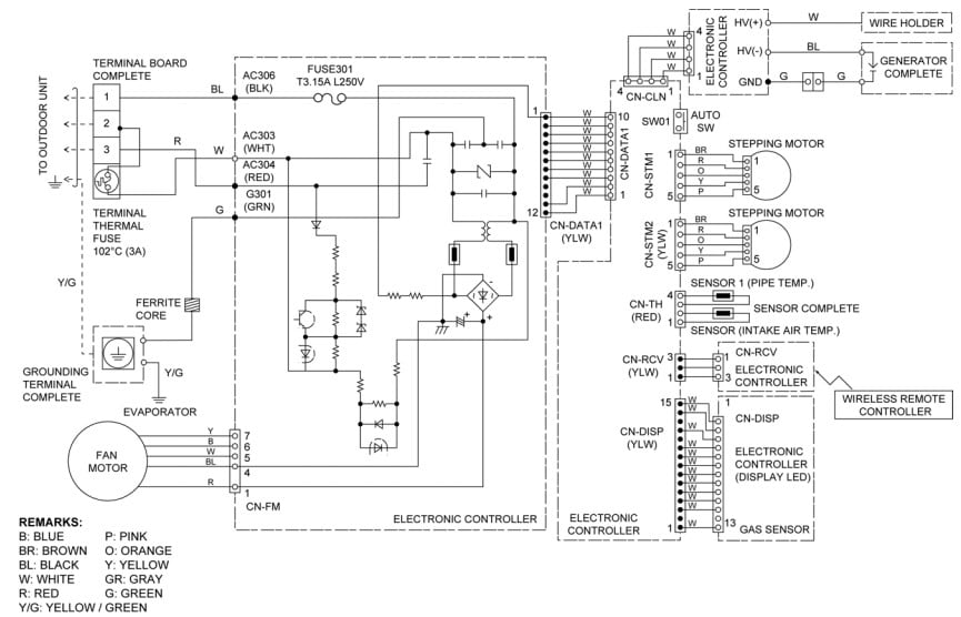
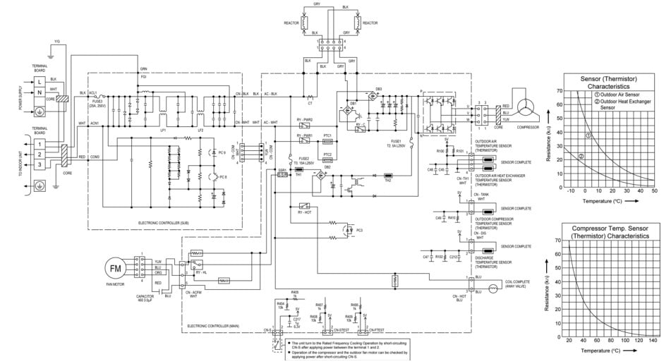
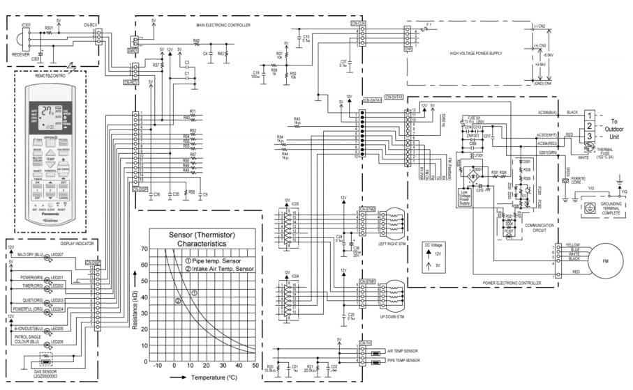
Manual Pdf
References
https://www.panasonic.com/global/hvac/air-conditioning.html
https://www.aircon.panasonic.eu/GB_en/applications/home/
- Midea VRF Error Codes and Self Diagnosis Explained - June 1, 2025
- Blueridge AC Error Codes and Troubleshooting - June 1, 2025
- Senville AC Error Codes – What Do They Mean - June 1, 2025
*If you can't find the code you're looking for on our site, please let us know, and we'll update our database as soon as possible.

F2 error, pls? How to fix?
H25 error code
Panasonic inverter 18btu. H25 error code
Error 71
my Panasonic cassette type unit shows error code H 35..