Gree is one of the largest Chinese appliance manufacturers that offers its appliances all over the world. With headquarters in Zhuhai, Guangdong – it is said to be the latest residential air conditioner manufacturer. Offering a wide range of selections to choose from, the company aims to offer something for every space in your home. Producing more than air conditioners the company aims to offer all small and large household appliances one might need on a daily basis.
Established in 1989, the company was revamped and named Gree Electric Appliances Inc. of Zhuhai in 1994. However, it operates with the name Gree worldwide. Despite being one of the best, there are times when their air conditioners show error codes. To help you out we have listed down some of the most common error codes for Gree Air conditioners.
Using their quick and easy fixes you can now get around the error codes without calling in a professional. Allowing you the ability to handle the situation without anyone’s help. The best way to deal with the situation is to note down the error code and match it using the list below. Once you have the error code you can easily work your way to the fix.
Split Type
| Error Codes | Meaning |
|---|---|
| E1 | Refrigerant system high pressure protection. During cooling and drying operation, except indoor fan operates, all loads stop operation. During heating operation, the complete unit stops. |
| E2 | Anti-freezing protection. During cooling and drying operation, compressor and outdoor fan stop while indoor fan operates. |
| E3 | Low pressure protection of compressor. The complete unit stops. |
| E4 | Compressor exhaust high temperature protection. During cooling and drying operation, compressor and outdoor fan stop while indoor fan operates. During heating operation, all loads stop. Please refer to the malfunction analysis (discharge protection, overload). |
| E5 | AC over-current protection. During cooling and drying operation, compressor and outdoor fan stop while indoor fan operates. During heating operation, all loads stop. |
| E6 | Communication failure between indoor unit and outdoor unit. During cooling operation, compressor stops while indoor fan motor operates. During heating operation, the complete unit stops. Refer to the corresponding malfunction analysis. |
| E8 | Anti-high temperature protection. During cooling operation: compressor will stop while indoor fan will operate. During heating operation, the complete unit stops. Refer to the malfunction analysis (overload, high temperature resistant). |
| F0 | Refrigerant Leakage Protection |
| F1 | Indoor ambient sensor open or short circuit |
| F2 | Indoor tube sensor open or short circuit |
| F3 | Outdoor ambient sensor open or short circuit. The unit will stop operation as it reaches the temperature point. During cooling and drying operation, compressor stops and indoor fan operates; During heating operation, the complete unit stops operation. |
| F4 | Outdoor tube sensor open or short circuit. During cooling and drying operation, compressor stops while indoor fan will operate; During heating operation, the complete unit will stop operation. Outdoor temperature sensor hasn’t been connected well or is damaged. Please check it by referring to the resistance table for temperature sensor). |
| F5 | Exhaust sensor open or short circuit. Outdoor discharge temperature sensor is open/short circuited. During cooling and drying operation, compressor will sop after operating for about 3 mins, while indoor fan will operate; During heating operation, the complete unit will stop after operating for about 3 mins. |
| F6 | Over load limit / drop frequency. All loads operate normally, while operation frequency for compressor is decreased. Refer to the malfunction analysis (overload, high temperature resistant). |
| F8 | Over current limit / drop frequency. All loads operate normally, while operation frequency for compressor is decreased. The input supply voltage is too low; System pressure is too high and overload. |
| F9 | High exhaust temperature limit / drop frequency. All loads operate normally, while operation frequency for compressor is decreased. |
| PH | Voltage for DC bus-bar is too high. During cooling and drying operation, compressor will stop while indoor fan will operate; During heating operation, the complete unit will stop operation. |
| P5 | Over compressor phase current protection. During cooling and drying operation, compressor will stop while indoor fan will operate; During heating operation, the complete unit will stop operation. Refer to the malfunction analysis (IPM protection, loss of synchronism protection and overcurrent protection of phase current for compressor. |
| b5 | Inlet tube sensor malfunction |
| L3 | Outdoor DC fan motor malfunction |
| b7 | Outlet tube sensor malfunction |
| FC | Door malfunction |
| FE | Compressor overload sensor malfunction |
| C5 | Jumper cap malfunction protection. Operation of remote controller or control panel is available, but the unit won’t act. There’s no jumper cap on the controller. Jumper cap is not inserted properly and tightly. Jumper cap is damaged. Controller is damaged. |
| H1 | Defrosting. Defrosting will occur in heating mode. Compressor will operate while indoor fan will stop operation. It’s the normal state. |
| H2 | Static clearing dust protection |
| H3 | Compressor over load protection. During cooling and drying operation, compressor will stop while indoor fan will operate; During heating operation, the complete unit will stop operation. |
| H4 | System abnormal protection. During cooling and drying operation, compressor will stop while indoor fan will operate; During heating operation, the complete unit will stop operation. |
| H5 | IPM protection. During cooling and drying operation, compressor will stop while indoor fan will operate; During heating operation, the complete unit will stop operation. |
| H6 | No feedback of indoor fan motor. Indoor fan, outdoor fan, compressor and electric heat tube stop operation. 2 minutes later, 4-way valve stops; horizontal louver stops at the current position. |
| H7 | Compressor loss step protection. During cooling and drying operation, compressor will stop while indoor fan will operate; During heating operation, the complete unit will stop operation. |
| HC | PFC protection. During cooling and drying operation, compressor will stop while indoor fan will operate; During heating operation, the complete unit will stop operation. |
| H0 | Heating anti-high temperature drop frequency. All loads operate normally, while operation frequency for compressor is decreased. |
| Lc | Startup failure. During cooling and drying operation, compressor will stop while indoor fan will operate; During heating operation, the complete unit will stop operation. |
| U2 | Compressor protection against loss of phase |
| HE | Compressor demagnetization protection |
| EE | Loading EEPROM malfunction. During cooling and drying operation, compressor will stop while indoor fan will operate; During heating operation, the complete unit will stop. Replace outdoor control panel AP1. |
| P6 | Communication failure between main board and driver board |
| P7 | IPM sensor circuit malfunction. During cooling and drying operation, compressor will stop while indoor fan will operate; During heating operation, the complete unit will stop. refer to the part three charging malfunction analysis of capacitor. Replace outdoor control panel AP1. |
| P8 | IPM high temperature protection. During cooling operation, compressor will stop while indoor fan will operate; During heating operation, the complete unit will stop. After the complete unit is de-energized for 20mins, check whether the thermal grease on IPM Module of outdoor control panel AP1 is sufficient and whether the radiator is inserted tightly. If it’s no use, please replace control panel AP1. |
| PU | Capacitor charge malfunction. During cooling and drying operation, compressor will stop while indoor fan will operate; During heating operation, the complete unit will stop. Refer to the part three charging malfunction analysis of capacitor. |
| PL | Voltage of DC bus-bar is too low. During cooling and drying operation, compressor will stop while indoor fan will operate; During heating operation, the complete unit will stop. |
| Pc | Current detect circuit malfunction or Current sensor malfunction |
| Ld | Compressor loss of phase protection |
| LE | Compressor locked rotary protection |
| EU | imit/decrease frequency due to high temperature of module. All loads operate normally, while operation frequency for compressor is decreased. Discharging after the complete unit is de-energized for 20mins, check whether the thermal grease on IPM Module of outdoor control panel AP1 is sufficient and whether the radiator is inserted tightly. If it’s no use, please replace control panel AP1. |
| U1 | Compressor phase current detection circuit malfunction. During cooling and drying operation, compressor will stop while indoor fan will operate; During heating operation, the complete unit will stop. Replace outdoor control panel AP1. |
| U3 | PN voltage drop protection. During cooling and drying operation, compressor will stop while indoor fan will operate; During heating operation, the complete unit will stop. Supply voltage is unstable. |
| U4 | Compressor reverse protection |
| U5 | AC current detect circuit malfunction. During cooling and drying operation, the compressor will stop while indoor fan will operate; During heating operating, the complete unit will stop operation. There’s circuit malfunction on outdoor unit’s control panel AP1, please replace the outdoor unit’s control panel AP1. |
| U7 | The four-way valve is abnormal. If this malfunction occurs during heating operation, the complete unit will stop operation. |
| U8 | Disconnection of the exhaust temperature sensor |
| U9 | Zero- crossing malfunction of outdoor unit. During cooling operation, compressor will stop while indoor fan will operate; during heating, the complete unit will stop operation. Replace outdoor control panel AP1. |
| FA | Over tube temperature drop frequency |
| FH | Anti-freezing limit / drop frequency. All loads operate normally, while operation frequency for compressor is decreased. Poor air-return in indoor unit or fan speed is too low. |
| oE | PFC module temperature protection/PFC module sensor malfunction |
Cassette Type
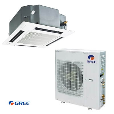
In case of malfunction (such as bad smell), turn off the power immediately and contact the service center. Do not repair the air conditioner by yourself. Incorrect repairs may cause fire. Please contact the service center. The appliance should not be used by children without supervision.
Once a failure occurs with the indoor unit in operation, the green unit LED flashes at intervals of 0.5 seconds.
The fault code is deduced from the number of times the green LED flashes, blocking unit operation. Between one flash cycle and the next one, a pause of 5 seconds elapses.
| Error Codes | Solution |
|---|---|
| E1 | High Pressure Protection. If outdoor unit detects the high pressure switch iscut off for 3-sec successively, high pressure protection will occur.All the loads (except the 4-way valve in heating mode) will be switched off. In thiscase, all the buttons and remote control signals except ON/OFF button will be disabled and system won't be recovered automatically. Switch off the unit or re-energize the unit after cutting off power to eliminate this protection. |
| E2 | Indoor Coil Freeze Protection. If indoor unit detects the evaporator temperature is lower than protective temperate value after the unit has been running for a period of time undercooling or dry mode, the unit will report this fault, in which case the compressor and outdoor fan motor will be stopped. The unit will not run until evaporator temperature is higher than the protective temp. value and the compressor is stopped for 3-min. |
| E4 | Compressor High Discharge Temperature Protection. f outdoor unit detects the discharge temperature is higher than protective temperature value, the unit will report high discharge temperature protection. If the protection occurs over 6 times, the unitcannot be recovered automatically. Switch off the unit or re-energize the unit aftercutting off power to reset this protection. |
| E6 | Communication Malfunction. If the outdoor unit does not receive data from indoor unit, communication malfunction will be reported. If there is communication abnormality between display board and indoor unit,communication malfunction will be reported. |
| E8 | Low Indoor Airflow. If the indoor unit does not receive signal from indoor fan motor for 30-secsuccessively when the fan motor is operating, indoor fan motor malfunction will be reported. In thiscase, the unitcan automatically resume operation after stopping. If the malfunction occurs 6 times within one hour, the unitcannot be recovered automatically. Switch off the unit or re-energize the unit after cutting off power to eliminate this malfunction. |
| E9 | Condensate Overflow Protection. If indoor unit detects the condensate overflow switch warning for 8-secsuccessively, the system will entercondensate overflow protection.The unit will shut off and will not recover automatically. Switch unit off and then switch it on to eliminate this malfunction. |
| F0 | Indoor Ambient Temperature Sensor at ReturnAir Inlet Malfunction. If indoor unit detects the indoor ambient temperature sensor is open circuit or shortcircuit for 5-secsuccessively, indoor ambient temp. sensor malfunction will be reported.The unitcan automatically resume operation after the malfunction disappears. If indoor ambient temperature sensor malfunction occurs in fan mode, only the error code is displayed and the indoor unit will operate normally. |
| F1 | Indoor Evaporator Coil Temperature Sensor Malfunction. If indoor unit detects the evaporator temperature sensor is open circuit or shortcircuit for 5-secsuccessively, evaporator temperature sensor malfunction will be reported.The unitcan automatically resume operation after the malfunction disappears. If evaporator temperature sensor malfunction occurs in fan mode, only the error code is displayed and the indoor unit will operate normally. |
| F2 | Indoor Condenser Coil Temperature Sensor Malfunction. If outdoor unit detects the condensercoil temperature sensor open circuit or shortcircuit for 5-secsuccessively,condensercoil temperature sensor malfunction will be reported.The unitcan automatically resume operation after the malfunction disappears. Ifcondenser temperature sensor malfunction occurs in fan mode, only the error code is displayed and the indoor unit will operate normally. |
| F3 | Outdoor Ambient Temperature Sensor Malfunction. If outdoor unit detects the outdoor ambient temperature sensor open circuit or shortcircuit for 5-secsuccessively, outdoor ambient temperature sensor malfunction will be reported.The unitcan automatically resume operation after the malfunction disappears. If outdoor ambient temperature sensor malfunction occurs in fan mode, only the errorcode is displayed and the indoor unit will operate normally. |
| F4 | Compressor Discharge Temperature Sensor Malfunction. If outdoor unit detects the compressor discharge temperature sensor is open circuit or shortcircuit for 5-secsuccessively after the compressor has been operating for 3-min, outdoor discharge temperature sensor malfunction will be reported.The unitcan automatically resume operation after the malfunction disappears. |
| F5 | Wired Controller Temp. Sensor Malfunction. If the wired Tether Controller detects open circuit or shortcircuit of its temperature sensor for 5-secsuccessively,wired controller temperature sensor malfunction will be reported. |
| H1 | Defrost Mode. System is defrosting outdoorcoil. |
| H3 | Compressor Overload Protection. If outdoor unit detects the compressor overload switch open within 3-sec successively, the unit will reportcompressor overload protection. If the fault occurs successively 3 times, the unit will not recover automatically. Switch off the unit or re-energize the unit to eliminate this protection. |
| H4 | Overload Protection. If indoor unit detects the evaporatorcoil temperature is higher than protective temp. value, the unit will report overload protection. The unit will restart operation after evaporator temperature is lower than the protective temp. value and the compressor is stopped for 3-minutes. If the protection occurs over 6 times, the unit will not recover automatically. Switch off the unit or re-energize the unit to eliminate this protection. |
| H6 | Outdoor Fan Motor Malfunction. If outdoor unit does not receive feedback signal from outdoor fan motor for 30-secsuccessively when the fan motor is operating, an outdoor fan motor malfunction will be reported. In thiscase, the unit can automatically resume operation after stopping. If the malfunction occurs 6 times within one hour, the unit will not recover automatically. Switch off the unit or re-energize the unit to eliminate this malfunction. |
| U7 | Reversing or 4-wayValve Malfunction. After the compressor starts operation in heating mode, if the outdoor unit detects the difference between evaporator temperature and indoor ambient temperature is lower than the protective value for 10-min successively, ReversingValve Malfunction will be reported and the outdoor unit will stop operation. If the malfunction occurs 3 times, the unit will not recover automatically. Switch off the unit or re-energize the unit to eliminate this malfunction. |

Cozy Series Inverter
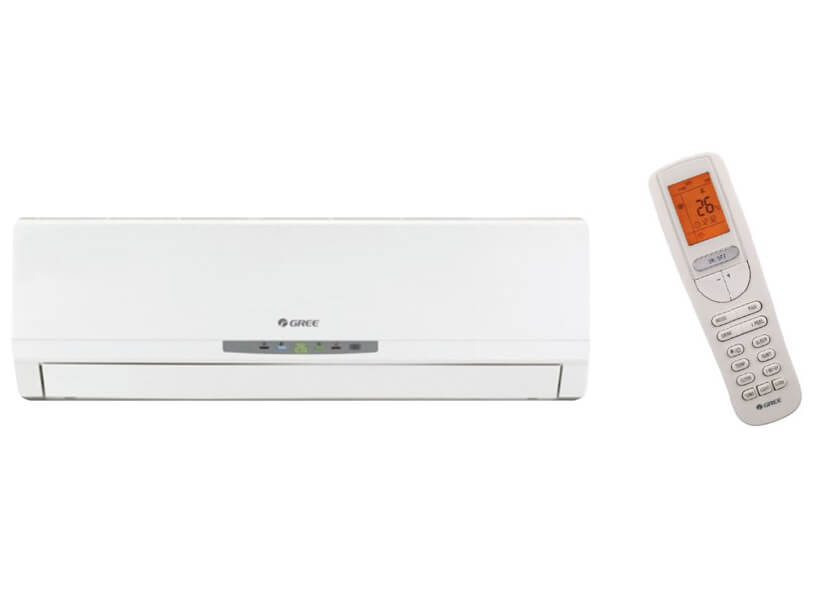
| Fault Codes | Solutions |
|---|---|
| E1 | High pressure protection of system |
| E2 | Antifreezing protection |
| F0 | In defect of refrigerant |
| E4 | High discharge temperature protection of compressor |
| E5 | Overcurrent protection |
| E6 | Communication Malfunction |
| E8 | High temperature resistant protection |
| EE | EEPROM malfunction |
| EU | Limit/ decrease frequency due to high temperature of module |
| C5 | Malfunction protection of jumper cap |
| Fo | Gathering refrigerant-Nominal cooling mode |
| F1 | Indoor ambient temperature sensor is open/short circuited |
| F2 | Indoor evaporator temperature sensor is open/short circuited |
| F3 | Outdoor ambient temperature sensor is open/short circuited |
| F4 | Outdoor condenser temperature sensor is open/short circuited |
| F5 | Outdoor discharge temperature sensor is open/short circuited |
| F6 | Limit/ decrease frequency due to overload |
| F8 | Decrease frequency due to overcurrent |
| F9 | Decrease frequency due to high air discharge |
| FH | Limit/ decrease frequency due to antifreezing |
| PH | Voltage for DC bus-bar is too high |
| PL | Voltage of DC bus-bar is too low |
| P0 | Compressor Min frequence in test state |
| P1 | Compressor rated frequence in test state |
| P2 | Compressor maximum frequence in test state |
| P3 | Compressor intermediate frequence in test state |
| P5 | Overcurrent protection of phase current for compressor |
| PU | Charging malfunction of capacitor |
| P7 | Malfunction of module temperature sensor circuit |
| P8 | Module high temperature protection |
| H0 | Decrease frequency due to high temperature resistant during heating operation |
| H2 | Static dedusting protection |
| H3 | Overload protection for compressor |
| H4 | System is abnormal |
| H5 | IPM protection |
| H5 | Module temperature is too high |
| H6 | Internal motor (fan motor) do not operate |
| H7 | Desynchronizing of compressor |
| HC | PFC protection |
| L3 | Outdoor DC fan motor malfunction |
| L9 | Power protection |
| LP | Indoor unit and outdoor unit doesn't match |
| LC | Failure startup |
| U1 | Malfunction of phase current detection circuit for compressor |
| U3 | Malfunction of voltage dropping for DC bus-bar |
| U5 | Malfunction of complete units current detection |
| U7 | The four-way valve is abnormal |
| U9 | Zerocrossing malfunction of outdoor unit |
Ductless Heat Pump
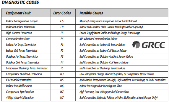
| Error Codes | Possible Causes |
|---|---|
| C5 | Indoor Configuration Jumper/Missing Configuration Jumper on Indoor Control Board |
| LP | Indoor/Outdoor Mismatch/Indoor and Outdoor Units Do Not Match |
| E5 | High Current Protection/Power Supply is not Stable and Voltage Range is too Large |
| E6 | Communication Error/Mis-wired or Communication Failure |
| F1 | Indoor Air Temp. Thermistor/Bad Connection, or Indoor Air Sensor Failure |
| F2 | Indoor Coil Temp. Thermistor/Bad Connection, or Indoor Coil Sensor Failure |
| F3 | Outdoor Air Temp. Thermistor/Bad Connection, or Outdoor Ambient Sensor Failure |
| F4 | Outdoor Coil Temp. Thermistor/Bad Connection, or Outdoor Coil Sensor Failure |
| F5 | Compressor Discharge Temp. Thermistor/Bad Connection, or Discharge Sensor Failure |
| H3 | Compressor Overload Protection/Low Refrigerant Charge |
| H5 | IPM Module Protection/IPM Module Temperature Too High |
| H6 | Indoor Fan Malfunction/Indoor Fan Stopped or Running too Slow |
| H7 | Compressor Synchronism/High Pressure, Low Voltage, or Bad Connections |
| U7 | 4-Way Valve Malfunction/Bad Connection, Solenoid Failure, or Valve Malfunction. |
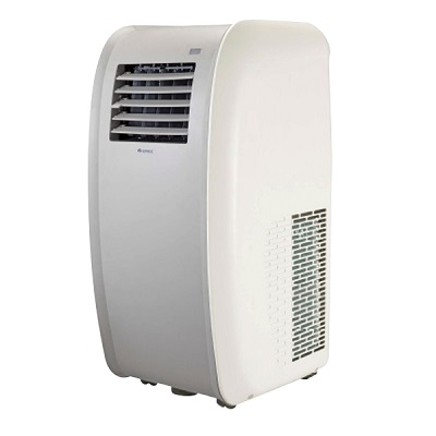
Portable AC
In some cases, problems can be solved easily without the help from the Customer Service department just by checking the following.
If the problem still persists after you check the following, then contact the Customer Service department.
| Codes | Cause |
|---|---|
| H8 | Chassis is full of water. Pour out the water inside chassis. |
| F1 | Malfunction of temperature sensor. |
| F2 | Malfunction of evaporator temperature sensor. |
| F0 | Refrigerant is leaking. System is blocked. Turn unit off, pull out power plug. Wait 30 minutes. Plug unit in and turn on. If code still appears, please contact Customer Service. |
| H3 | Overload protection for compressor-Overload malfunction. Check if the unit is within hightemperature, high-humidity environment. If outside temperature or humidity is too high, turn off unit. Wait until outside temperature drops to under 95˚F (35˚C). Check if the evaporator and condenser are blocked. If yes, remove objects. Turn unit off. Wait 30 minutes. |
| E8 | Overload malfunction. Check if the unit is within hightemperature, high-humidity environment. If outside temperature or humidity is too high, turn off unit. Wait until outside temperature drops to under 95˚F (35˚C). Check if the evaporator and condenser are blocked. If yes, remove objects. Turn unit off. Wait 30 minutes. |
| F4 | Outdoor tube temperature sensor is open/short-circuited. |
| E5 | Overcurrent protection. Turn unit off, pull out power plug. Wait10 minutes. Plug unit in and turn on. |
Remote Control
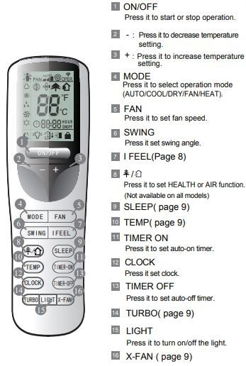
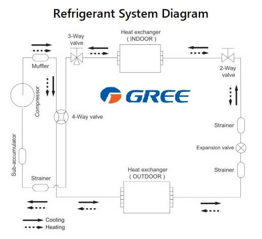
Diagram
Manuals PDF
Livo Split Air Conditioner Manual
Gree AC Installation and Service Manual
Ductless Inverter Heat Pump AC Manual
Multi VRF Air Conditioner Manual PDF
Cassette Type Aircon Error Codes
Inverter AC Owner Manual GWH-K3DN
Owner Manual – Operation Instructions for Split Versati
Inverter AC Console Type – Owner Manual GEH09AA-K6DNA1E PDF
DC Inverter U-match Series Floor Ceiling Type Unit GTH09K3FI – GUHD09NK3FO
Service Manual GWH09QB-K3DNA6D (WIFI)
Commercial Air Conditioners Owners Manual – GMV DC Inverter VRF Models GMV-785W
Inverter AC Console Type – Owner Manual
References
gree-america.com/hvac america/resource/
greecomfort.com/assets/documents/archive/livo-revision-a/owner-s-manual.pdf
- Unionaire Air Conditioner Error Codes - December 1, 2025
- Ameristar AC Error Codes and Troubleshooting - December 1, 2025
- Rheem Pool Heat Pump Error Codes - December 1, 2025

How can I solve this problem H3
I have an F0 error code. I have read as much as I can and still will not get cold. What do I do? Just bought it today.
hello
gree spilet install error f0
what is un error f0
please guide me?
I have gree 18000 btu inverter air condition error corde H7 pls tell me solution.
From la curacao
I have gree 18000 btu and showing PH error. How to fix it ? please help!!!
I got 2 installation of gree inverter 1 is working ok and second one is not working.its indicates LP.all connection is ok.can’t find the trouble.please help.