Carrier is one of the oldest multinational corporations in the world, established in 1915 the company was one of the few that manufactured every single appliance part on its own. Building systems that lasted decades the company was solely focused on putting out appliances that make a name for themselves. Over the past decades, the company has gained a lot of achievements making them one of the few that have created a solid standing around the world.
Settled in more than 106 countries, Carrier is now available in six continents. Offering a wide range of appliances while keeping its main focus on its original air conditioning and heating system. These include air conditioning and heating solutions for residential and commercial buildings. One of the most promising appliances the company offers is its chillers which ensure smooth workings in various conditions.
When facing an error code we suggest you grab a pen and paper to note down the code rather than pressing various buttons on your Carrier Chiller. This way you will not risk damaging your appliance any further and will be able to find out the exact issue using the common error code list for Carrier Chiller error codes listed below. Once you nail down the issue you can easily call in a professional, or fix the issue yourself.
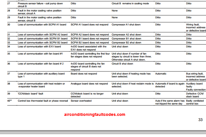
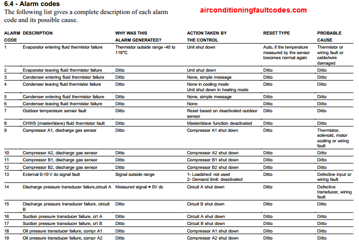
Alarm Codes
The following list gives a complete description of each alarm code and its possible cause.
| Alarm Codes | Description |
|---|---|
| 1 | Evaporator entering fluid thermistor failure |
| 2 | Evaporator leaving fluid thermistor failure |
| 3 | Condenser entering fluid thermistor failure |
| 4 | Condenser leaving fluid thermistor failure |
| 5 | Condenser entering fluid thermistor failure |
| 6 | Condenser leaving fluid thermistor failure |
| 7 | Outdoor temperature sensor fault |
| 8 | CHWS (master/slave) fluid thermistor fault |
| 9 | Compressor A1, discharge gas sensor |
| 10 | Compressor A2, discharge gas sensor |
| 11 | Compressor B1, discharge gas sensor |
| 12 | Compressor B2, discharge gas sensor |
| 13 | External 0-10 V dc signal fault |
| 14 | Discharge pressure transducer failure,circuit A |
| 15 | Discharge pressure transducer failure, circuit B |
| 16 | Suction pressure transducer failure, crt A |
| 17 | Suction pressure transducer failure, crt B |
| 18 | Oil pressure transducer failure, compr A1 |
| 19 | Oil pressure transducer failure, compr A2 |
| 20 | Oil pressure transducer failure, compr B1 |
| 21 | Oil pressure transducer failure, compr B2 |
| 22 | Economizer A1 transducer failure |
| 23 | Economizer A2 transducer failure |
| 24 | Economizer B1 transducer failure |
| 25 | Economizer B2 transducer failure |
| 26 | Pressure sensor failure - coil pump down circuit A |
| 27 | Pressure sensor failure - coil pump down circuit B |
| 28 | Fault in the motor cooling valve position sensor, circuit A |
| 29 | Fault in the motor cooling valve position sensor, circuit B |
| 30 | Loss of communication with SCPM A1 board |
| 31 | Loss of communication with SCPM A2 board |
| 32 | Loss of communication with SCPM B1 board |
| 33 | Loss of communication with SCPM B2 board |
| 34 | Loss of communication with EXV board |
| 35 | Loss of communication with fan board #1 |
| 36 | Loss of communication with fan board # 2 |
| 37 | Loss of communication with auxiliary board type 1 |
| 38 | Loss of communication with heat reclaim or evaporator heater board |
| 39 | 'CCN/clock board' fault |
| 40 | Control box thermostat fault or phase reversal |
| 41 | Unit emergency stop |
| 42 | Initial factory configuration required |
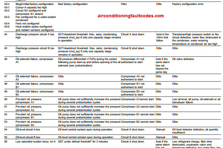
| 43-n | Illegal initial factory configuration |
| 43-1 | Compr A capacity too high |
| 43-2 | Compr B2 configured and compressor B1 absent |
| 43-3 | Fan configured for a water-cooled condenser |
| 43-4 | Fans not configured |
| 43-5 | Heat reclaim option configured and reclaim sensors configured |
| 44 | Discharge pressure circuit A too high |
| 45 | Discharge pressure circuit B too high |
| 46 | Oil solenoid failure, compressor A1 |
| 47 | Oil solenoid failure, compressor A2 |
| 48 | Oil solenoid failure, compressor B1 |
| 49 | Oil solenoid failure, compressor B2 |
| 50 | Pre-start oil pressure, compressor A1 |
| 51 | Pre-start oil pressure, compressor A2 |
| 52 | Pre-start oil pressure, compressor B1 |
| 53 | Pre-start oil pressure, compressor B2 |
| 54 | Oil level circuit A low |
| 55 | Oil level circuit B low |
| 56 | Low saturated suction temp, crt A |
| 57 | Low saturated suction temp, circuit B |
| 58 | High saturated suction temp, circuit A |
| 59 | High saturated suction temp, crt B |
| 60 | Low discharge superheat, circuit A |
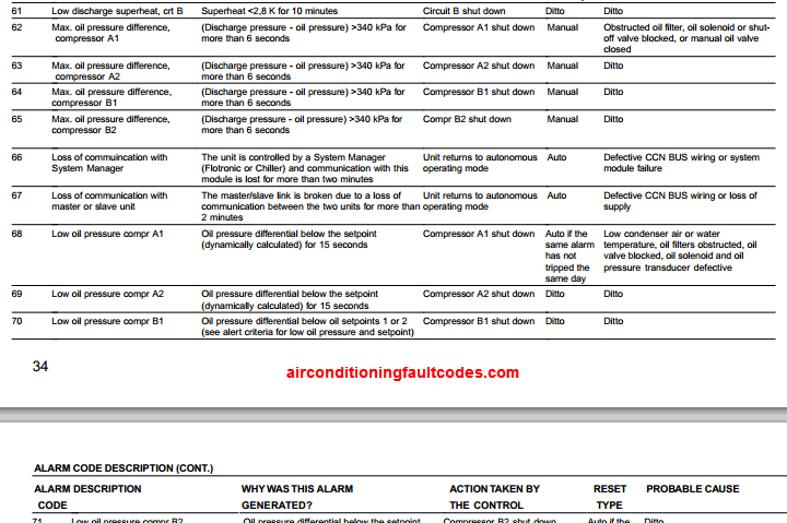
| 61 | Low discharge superheat, crt B |
| 62 | Max. oil pressure difference, compressor A1 |
| 63 | Max. oil pressure difference, compressor A2 |
| 64 | Max. oil pressure difference, compressor B1 |
| 65 | Max. oil pressure difference, compressor B2 |
| 66 | Loss of commuincation with System Manager |
| 67 | Loss of communication with master or slave unit |
| 68 | Low oil pressure compr A1 |
| 69 | Low oil pressure compr A2 |
| 70 | Low oil pressure compr B1 |
| 71 | Low oil pressure compr B2 |
| 72 | Evaporator frost protection |
| 73 | Condenser frost protection, circuit A |
| 74 | Condenser frost protection, circuit B |
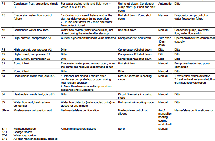
| 75 | Evaporator water flow control failure |
| 76 | Condenser water flow loss |
| 77 | High current, compressor A1 |
| 78 | High current, compressor A2 |
| 79 | High current, compressor B1 |
| 80 | High current, compressor B2 |
| 81 | Pump 1 fault |
| 82 | Pump 2 fault |
| 83 | Heat reclaim mode fault, circuit A |
| 84 | Heat reclaim mode fault, circuit B |
| 85 | Water flow fault, heat reclaim condenser |
| 86-nn | Master/slave configuration fault |
| 87-n | Maintenance alert |
| 87-1 | Charge too low |
| 87-2 | Water loop too low |
| 87-3 | Air filter maintenance delay elapsed |
| 87-4 | Pump 1 maintenance delay elapsed |
| 87-5 | Pump 2 maintenance delay elapsed |
| 87-6 | Water filter maintenance delay elapsed |
- 30GX and 30HXC series
- PRO-DIALOG Control
- Screw-Compressor Air- and
- Water-Cooled Liquid Chillers
- 50 Hz
The PRO-DIALOG Plus control system has many fault tracing aid functions. The local interface and its various menus give access to all unit operating conditions. The test function makes it possible to run a quick test of all devices on the unit. If an operating fault is detected, an alarm is activated and an alarm code is stored in the Alarm menu.
Diagnostics and Troubleshooting
Resetting Alarm Codes
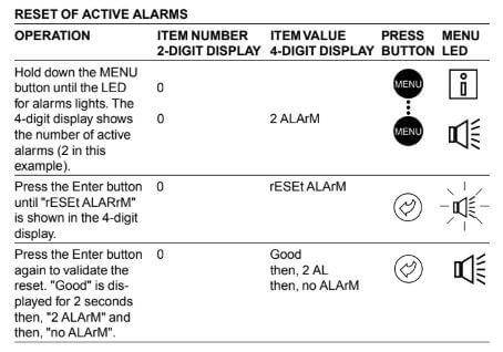
When the cause of the alarm has been corrected the alarm can be reset, depending on the type, either automatically on return to normal, or manually when action has been taken on the unit. Alarms can be reset even if the unit is running. This means that an alarm can be reset without stopping the machine. In the event of a power supply interrupt, the unit restarts automatically without the need for an external com- mand. However, any faults active when the supply is inter- rupted are saved and may in certain cases prevent a circuit or a unit from restarting. A manual reset must be run from the main interface using the following procedure:
Reset of Active Alarms
Manuals Pdf
Air-cooled screw chillers 30xa installation, operation and maintenance manual
- Unionaire Air Conditioner Error Codes - December 1, 2025
- Ameristar AC Error Codes and Troubleshooting - December 1, 2025
- Rheem Pool Heat Pump Error Codes - December 1, 2025

We have carrier chiller model126008648 which has alarm 46 on the display. Please tell what to check
Pak kalau code alarm 105 chiller carrier screw kemungkinan besar dari apanya nya tolong bantuannya terima kasih
Hi Brothers
i need some advise on fault that am receiving on our carrier Chiller it shows WATER EXCHANGER TEMPERATURE SENSOR SWAPPED.
Any one knows about the cause of this fault?
thank you
Kodec error chiller carrier 84/85/86
Penyebab kode error itu masalah apa?
carrier chiller shows error trip out