Carrier Global Corporation founded in 1915, is an American multinational home appliance company that came forward as an independent manufacturer and distributor of air conditioning and heating ventilating systems. With a headquarter in Palm Beach Gardens, Florida – the company has made an impact worldwide. Offering commercial and residential appliances and equipment.
With customers in 106 countries Carrier is said to be one of the few corporations that serve six continents. Offering a wide range of appliances, including residential and commercial air conditioners. While the company has a great track record, there are times when buyers find themselves facing an error code. While some might call for help, we feel it’s best to try and deal with the situation on your own. As most errors come with a simple and easy fix you can take on your own.
The best way to deal with the situation is to note down the error code and match it using the list below. Once you have the error code you can easily work your way to the fix. To help you out we have listed down some of the most common error codes for Carrier Air conditioners. These can help you regain control over your appliance, and ensure a smooth and fully functional system.
The printed circuit boards existing inside the indoor unit are equipped with self-diagnostic function to detect malfunction and automatically stops the operation at the air conditioner after blinking of power or timer led as per malfunction.
Indoor Unit Codes
| Error Codes | Meaning |
|---|---|
| E0 | Indoor unit EEPROM parameter error |
| E1 | Indoor / outdoor units communication error |
| E3 | Indoor fan speed has been out of control |
| E4 | Indoor room temperature sensor T1 open circuit or shortcircuit |
| E5 | Evaporator coil temperature sensor T2 open circuit or short circuit |
| EC | Refrigerant Leakage Detection |
| F1 | Outdoor ambient temperature sensor T4 open circuit or short circuit |
| F2 | Condenser coil temperature sensor T3 open circuit or short circuit |
| F3 | Compressor discharge temperature sensor T5 open circuit or short circuit |
| F4 | Outdoor unit EEPROM parameter error |
| F5 | Outdoor fan speed has been out of control |
| P0 | IPM malfunction or IGBT over-strong current protection |
| P1 | Over voltage or over low voltage protection |
| P2 | High temperature protection of compressor top diagnosis and solution |
| P4 | Inverter compressor drive error |
| P5 | Mode conflict |
| P6 | Compressor voltage protection |
Outdoor Unit Codes
| Error Codes | Meaning |
|---|---|
| E0 | Outdoor EEPROM malfunction |
| E2 | Indoor/outdoor units communication error |
| E3 | Communication malfunction between IPM board and outdoor main board |
| E4 | Open or short circuit of outdoor unit temperature sensor |
| E5 | Voltage protection |
| E8 | Outdoor fan speed malfunction |
| F1 | No A Indoor unit coil outlet temperature sensor or connector of sensor is defective |
| F2 | No B Indoor unit coil outlet temperature sensor or connector of sensor is defective |
| F3 | No C Indoor unit coil outlet temperature sensor or connector of sensor is defective |
| F4 | No D Indoor unit coil outlet temperature sensor or connector of sensor is defective |
| F5 | No E Indoor unit coil outlet temperature sensor or connector of sensor is defective |
| P1 | High pressure protection |
| P2 | Low pressure protection |
| P3 | Current protection of compressor |
| P4 | Temperature protection of compressor |
| P5 | High temperature protection of condenser |
| P6 | IPM module protection |
Outdoor Check Function
| Codes | Meaning |
|---|---|
| 00 | Normal display |
| 01 | Number of indoor units in good connection |
| 02 | Outdoor unit running mode |
| 03 | A indoor unit capacity HP |
| 04 | B indoor unit capacity HP |
| 05 | C indoor unit capacity HP |
| 06 | D indoor unit capacity HP |
| 07 | E indoor unit capacity HP |
| 08 | A Indoor unit capacity demand code |
| 09 | B Indoor unit capacity demand code |
| 10 | C Indoor unit capacity demand code |
| 11 | D Indoor unit capacity demand code |
| 12 | E Indoor unit capacity demand code |
| 13 | Total indoor units amendatory capacity demand code |
| 14 | Target frequency corresponding to the total indoor units amendatory capacity demand |
| 15 | Target frequency after the frequency limit |
Judgment by Flashing LED of Indoor Unit
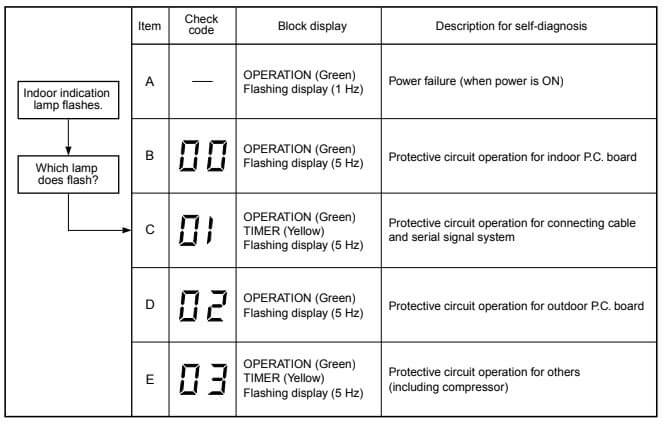
Notes:
- The contents of items B and C and a part of item E are displayed when air conditioner operates
- When item B and C, and item B and a part of item E occur concurrently, priority is given to the block of item B.
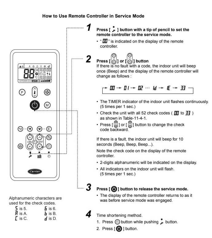
- The check codes can be confirmed on the remote controller for servicing.
Caution at Servicing:
- After servicing, push the [Θ] button to return to the normal mode.
- After servicing by the check code, turn off breaker of the power supply, and turn on breaker of the power supply again so that memory in the microcomputer returns the initial status. However, the check codes are not deleted even if the power supply is turned off because they are stored in the fixed memory.
| Codes | Cause |
|---|---|
| 0C | Short-circuit or disconnection of the room temperatur sensor (TA sensor) |
| 0d | Being out of place, disconnection, short-circuit, or migration of heat exchanger sensor (TC sensor) |
| 11 | Lock of indoor fan or trouble on the indoor fan circuit |
| 12 | Trouble on other indoor P.C. boards |
| 04 | Return serial signal is not sent to indoor side from operation started. (1) Defective wiring of connecting cable (2) Operation of compressor thermo. Gas shortage Gas leak |
| 05 | Operation command signal is not sent to outdoor side |
| 14 | Inverter over-current protective circuit operates. (Short time) |
| 16 | Position-detect circuit error or short-circuit between windings of compressor |
| 17 | Current-detect circuit error |
| 18 | Being out of place, disconnection or short- circuit of outdoor temp. sensor |
| 19 | Disconnection or short- circuit of discharge temp. sensor |
| 1A | Outdoor fan drive system error |
| 1b | Outdoor heat exchanger temp. sensor error |
| 1C | Compressor drive output error, Compressor error (lock, missing, etc.), Break down |
| 07 | Return serial signal has been sent when operation started, but it is not sent from halfway |
| 1d | Compressor does not rotate |
| 1E | Discharge temp. exceeded 117°C |
| 1F | Break down of compressor |
| 08 | Four-way valve inverse error |
Infinity Series Air Conditioners
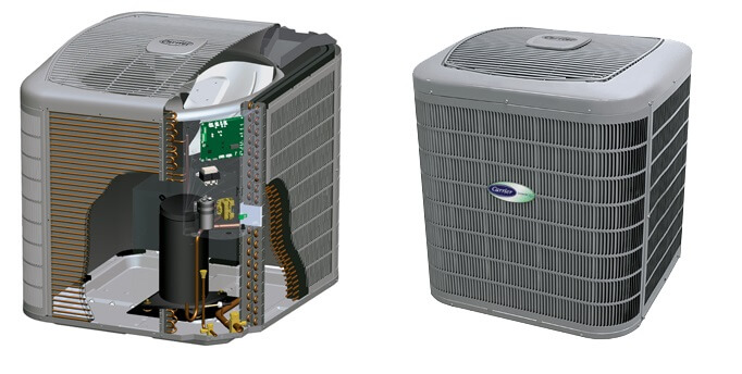
The codes are flashed by a series of short and long flashes of the status light. The short flashes indicate the first digit in the status code, followed by long flashes indicating the second digit of the error code. The short flash is 0.25 seconds ON and the long flash is 1.0 second ON. Time between flashes is 0.25 seconds. Time between short flash and first long flash is 1.0 second. Time between code repeating is 2.5 seconds with LED OFF. Count the number of short and long flashes to determine the appropriate flash code. Table 6 gives possible causes and actions related to each error.


Inverter Window Room AC
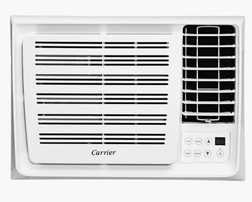
Operate the fan without cooling until the frost disappears. Sometimes a breaker will look like it is in the operating position but is actually tripped. Be sure to flip the breaker lever to ‘OFF’ and then back to “ON’ with the corresponding click.
| Error Codes | Solutions |
|---|---|
| E1 | Loss of communication between the CCC 2 thermostat and an individual system power module board. The LED will display error code EI and the zone number that lost communication. Any additional zones that loose communication will blink in addition to the current zone. |
| E2 | Open circuit or out-of-range indoor temperature sensor. All heat , cool, and dehumidify operations will be locked out. Manual fan operation will continue. |
| E3 | Indoor Temperature Sensor. All heat, cool, and dehumidify operation will be locked out. Manual fan operation will continue. |
| E4 | Open circuit or out of range Outdoor Temperature Sensor (select models). Heat pump and dehumidification operation will be locked out. Air conditioner, furnace, heat strip and fan operation can continue to operate. |
| E5 | Open circuit or out of range Freeze Sensor. Air conditioner and dehumidification operation will be locked out. Heat pump, furnace, heat strip and fan operation can continue to operate but displays the last temperature set-point. |
| E6 | Open circuit Humidity Sensor (Select Models). Air conditioner and dehumidification will be locked out. Heat pump, furnace heat strip and fan can continue to operate. |
| E7 | Loss of 120 VAC power to all power module boards on the system. The system will shut down. |
| E8 | Invalid zone configuration. The heat pump and heat strip DIP switches are both set to the ON position in one zone. Heat pump, heat strip, air conditioner, and dehumidify operation will be locked out in the affected zone. |
| E9 | Invalid zone configuration. The dehumidifier DIP switch and either the heat pump or heat strip DIP switches are set to the ON position in one zone. Heat pump, heat strip, air conditioner, and dehumidify operation will be locked out in the affected zone. |
Other Models Fault Codes
| Fault Code | Solution |
|---|---|
| nF | Air Filter Replacement Reminder: After 2,880 hours of use, the display window on the indoor unit will flash “nF.” This is a reminder to replace your filter. After 15 seconds, the unit will revert to its previous display. To reset the reminder, press the LED button on your remote control 4 times, or press the MANUAL CONTROL button 3 times. If you don’t reset the reminder, the “nF” indicator will flash again when you restart the unit. |
| cl | Air Filter Cleaning Reminder: After 240 hours of use, the display window on the indoor unit will flash “CL.” This is a reminder to clean your filter. After 15 seconds, the unit will revert to its previous display. To reset the reminder, press the LED button on your remote control 4 times, or press the MANUAL CONTROL button 3 times. If you don’t reset the reminder, the “CL” indicator will flash again when you restart the unit. |
| ec | Refrigerant Leakage Detection: The indoor unit will automatically display “EC” The “timer” indicator light turns off and the “run” indicator light flashes 7 times when the unit detects refrigerant leakage. |
| BL | Filter cleaning Reminding. |
| ed | Alarm Light Flashing Slow (Outdoor Unit Error) (40WAW024 only). Outdoor unit fault. |
| EE | Alarm Light Flashing Fast (Water Level Error) (40WAW024 only). - Loose connection or disconnected at port on PC board. Tighten the connection or reconnect at port on PC board. - Loose connection or disconnected at port on PC board. Tighten the connection or reconnect at port on PC board. - Drain pump faulty. Replace the drain pump |
| FE | Operation and Timer Lights Flashing Fast Together (Address Error) Indoor unit without address. Run automatic addressing option at the outdoor unit. Use remote wireless or wired controller to readdress indoor unit. |
| FR | Lack of refrigerant |
Performance Series Fault Codes
Performance Residential Ductless Multi-Split Heat Pump System. Multi-Split High-Wall Ductless Split System 38GVM.
| Error Codes | Trouble |
|---|---|
| 08 | Defrost Mode 1 |
| 0A | Defrost Mode 2 |
| F0 | Low charge or refrigeration system blockage |
| F3 | Outdoor ambient temperature sensor malfunction |
| F4 | Outdoor mid-coil temperature sensor malfunction |
| F5 | Outdoor discharge air temperature sensor |
| F7 | Cooling oil return cycle |
| E1 | System high pressure protection |
| E2 | Indoor freeze protection |
| E3 | System low pressure protection |
| E4 | Compressor discharge high temperature protection |
| E6 | Communication error between indoor and outdoor |
| E7 | Mode conflict |
| E8 | System overload protection |
| E9 | Cold Blow Protection |
| dd | Test mode |
| Fo | Pump down mode |
| P0 | IPM Rest |
| P5 | Compressor current protection |
| P6 | Communication error between the inverter drive and main board |
| P7 | Heat sink temperature sensor malfunction |
| P8 | IPM over temperature protection |
| P9 | Open Contactor |
| Pc | Current sensor malfunction |
| Pd | Current sensor mis-wiring protection |
| PA | Input current protection |
| PF | Inverter board ambient temperature sensor malfunction |
| PL | Low voltage protection |
| PH | High voltage protection |
| PP | Abnormal input AC voltage |
| PU | Capacitor charging malfunction |
| H1 | Heating oil return cycle |
| H2 | Forced defrost |
| H3 | Compressor overheat protection |
| H5 | IPM Protection |
| H7 | Compressor speed reduction |
| Hc | PFC board protection |
| L9 | Compressor high voltage protection |
| Lc | Compressor start-up failure |
| Ld | Compressor phase loss protection |
| LE | Compressor stalling |
| LF | Compressor over-speed protection |
| A5 | Condenser coil inlet temp sensor malfunction |
| A7 | Condenser outlet temperature sensor malfunction |
| EE | Memory card error |
| En | Frequency limitation for module circuit protection |
| EU | Frequency limitation for module temperature protection |
| F6 | Frequency limitation for overload protection |
| F8 | Frequency limitation for system circuit protection |
| F9 | Frequency limitation for module circuit protection |
| FH | Frequency limitation for freeze protection |
| HE | Compressor demagnetizing protection |
| LP | Indoor and outdoor units mismatch |
| U1 | Compressor phase detection malfunction |
| U3 | Low DC bus voltage |
| dn | Communication error between main board and EXV |
| 13 | Unit A indoor pipe outlet temperature sensor malfunction |
| 14 | Unit A indoor pipe inlet temperature sensor malfunction |
| 15 | Unit A Indoor return air sensor malfunction |
| 16 | Unit A mode conflict |
| 17 | Unit A freeze protection |
| 23 | Unit B indoor pipe outlet temperature sensor malfunction |
| 24 | Unit B indoor pipe inlet temperature sensor malfunction |
| 25 | Unit B Indoor return air sensor malfunction |
| 26 | Unit B mode conflict |
| 27 | Unit B freeze protection |
| 33 | Unit C indoor unit pipe outlet temperature sensor malfunction |
| 34 | Unit C indoor unit pipe inlet temperature sensor malfunction |
| 35 | Unit C Indoor unit return air sensor malfunction |
| 36 | Unit C mode conflict |
| 37 | Unit C freeze protection |
| 41 | Unit D communication error |
| 42 | Indoor return air temperature sensor malfunction |
| 43 | Unit D indoor pipe outlet temperature sensor malfunction |
| 44 | Unit D indoor pipe inlet temperature sensor malfunction |
| 45 | Unit D Indoor return air temperature sensor malfunction |
| 46 | Unit D mode conflict |
| 47 | Unit D freeze protection |
| 51 | Unit E communication error |
| 52 | Unit E indoor pipe midway temperature sensor malfunction |
| 53 | Unit E indoor pipe outlet temperature sensor malfunction |
| 54 | Unit E indoor pipe inlet temperature sensor malfunction |
| 55 | Unit E Indoor return air temperature sensor malfunction |
| 56 | Unit E mode conflict |
| 57 | Unit E freeze protection |
| C5 | Jumper missing on replacement indoor board |
Aircon Split Malfunction Indicator
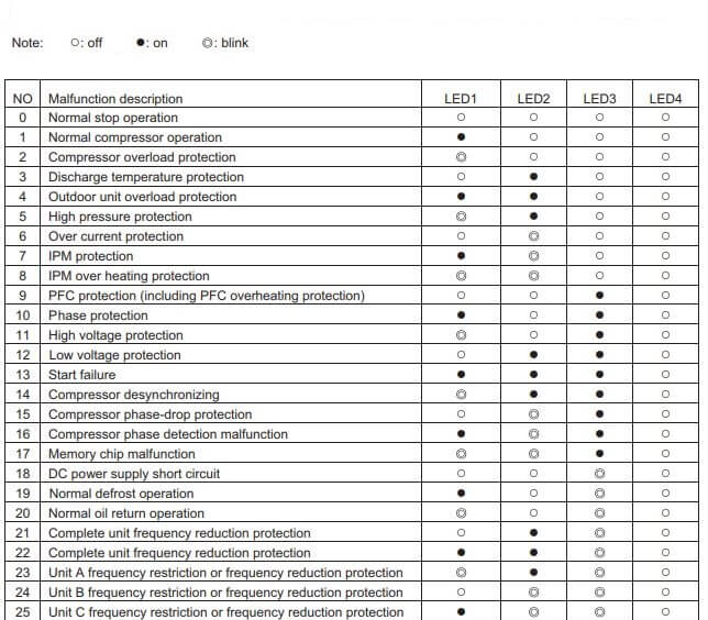
When several malfunctions occur at the same time, they will be displayed in circulation and every malfunction is displayed for 5s.
Note: o: off ●: on o: blink
How to Use Remote Controller in Service Mode?
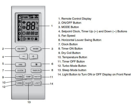
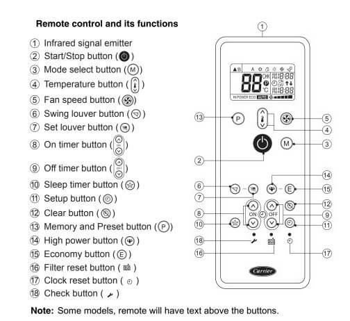
Remote Control Buttons Meaning
Manuals Pdf
Split Air Conditioner Manual 2
References
carrierair.com.au/installer-and-technical-support/service-manuals/
- Unionaire Air Conditioner Error Codes - December 1, 2025
- Ameristar AC Error Codes and Troubleshooting - December 1, 2025
- Rheem Pool Heat Pump Error Codes - December 1, 2025

Cassete type error code pls, show now?
my carrier window inverter indicates E everytime i touch na remote ? Whats the problem!