Goodman Manufacturing is an American-based company that operates as an independent subsidiary of the Daikin Group. The largest manufacturer of heating, air conditioning, and ventilation systems in the world. Founded back in 1975 in Waller, Texas – they only offered residential cooling and heating systems for the area.
Founded by HVAC dealer Harold V. Goodman the company manufactured flexible air ducts and plastic blade registers. Which was taken to another level when Harold tried to fulfill his dreams of offering an affordable HVAC system for households around the world. However, it was not until 1982 that the company entered the HVAC market and expanded its product offerings.
Goodman might be a high-ranking company, but from time to time customers have complained about system errors. Fortunately, most of these errors can be fixed on your own. So rather than ignoring the error codes, your appliance is showing its time to note down the Goodman air conditioner error code and get to the bottom of the problem. To help you out we have listed down the most common error codes of Goodman air conditioners.
Most Common Codes
A2: Shorted sensor / Open sensor / Sensor disconnected / Sensor out of range.
A3: Shorted sensor / Open sensor / Sensor disconnected / Sensor out of range.
E5: Short in low voltage wiring.
EE: Compressor relay contacts welded.
b0: Indoor blower motor problem / Communications errorbetween indoor and outdoor unit.
b9: Indoor blower motor problem / Blocked filters / Restrictive / undersized ductwork / Indoor-outdoor unit miss match.
d0: Air conditioner / heat pump is wired as part of a communicating system and integrated control module does not contain any shared data.
d1: Air conditioner / heat pump is wired as part of a communicating system and integrated control module contains invalid shared data or network data is invalid for the integrated control module.
d2: Air conditioner / heat pump is wired as part of a communicating system and outdoor unit requires airflow greater than indoor unit’s airflow capability / Shared data is incompatible with the system or missing parameters.
d3: Shared data sent to integrated control module does not match hardware configuration.
d4: Shared data on memory card has been rejected.
01: Low refrigerant charge / Restriction in liquid line / Indoor blower motor failure.Indoor thermostat set extremely low.
02: Blocked condenser coil / Outdoor fan not running.
03: Intermittent thermostat demand / Faulty compressor relay.
04: Compressor bearings are seized / Failed compressor run capacitor / Faulty run capacitor wiring / Faulty compressor wiring / Low line voltage.
05: Power is disconnected / Failed compressor protector / Compressor not properly wired to control.
06: Compressor start winding is open / Failed compressor run capacitor / Faulty run capacitor wiring / Compressor not properly wired to control / Faulty compressor wiring.
07: Compressor run winding is open /Compressor no properly wired to control /Faulty compressor wiring.
08: Low line voltage / High line voltage.
09: Control detects secondary voltage less than 18 VAC / Transformer overloaded / Low line voltage.
Not displayed, No current through run or start windings / Compressor run winding is open / Compressor not properly wired to control / Faulty compressor wiring / Failed compressor run capacitor / Faulty run capacitor wiring.
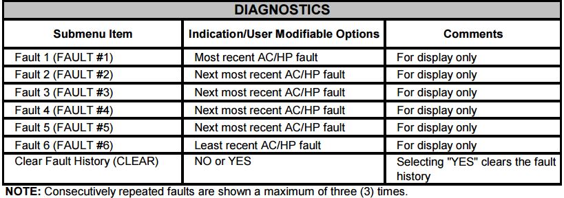
Troubleshooting
Status LED: Green “POWER”
Status LED Description: Module has power
Status LED Troubleshooting: Supply voltage is present at module terminals
Status LED: Red “TRIP”
Status LED Description: Thermostat demand signal Y1 is present, but the compressor is not running
Status LED Troubleshooting:
- Compressor protector is open
- Outdoor unit power disconnect is open
- Compressor circuit breaker or fuse(s) is open
- Broken wire or connector is not making contact
- Low pressure switch open if present in system
- Compressor contactor has failed open
Status LED: Yellow “ALERT” Flash Code 1
Status LED Description: Long Run Time, Compressor is running extremely long run cycles
Status LED Troubleshooting:
- Low refrigerant charge
- Evaporator blower is not running
- Evaporator coil is frozen
- Faulty metering device
- Condenser coil is dirty
- Liquid line restriction (filter drier blocked if present in system)
- Thermostat is malfunctioning
Status LED: Yellow “ALERT” Flash Code 2
Status LED Description: System Pressure Trip Discharge or suction pressure out of limits or compressor overloaded
Status LED Troubleshooting:
- High head pressure
- Condenser coil poor air circulation (dirty, blocked, damaged)
- Condenser fan is not running
- Return air duct has substantial leakage
- If low pressure switch present in system, check Flash Code 1 information
Status LED: Yellow “ALERT” Flash Code 3
Status LED Description: Short Cycling Compressor is running only briefly
Status LED Troubleshooting:
- Thermostat demand signal is intermittent
- Time delay relay or control board defective
- If high pressure switch present go to Flash Code 2 information
- If low pressure switch present go to Flash Code 1 information
Status LED: Yellow “ALERT” Flash Code 4
Status LED Description: Locked Rotor
Status LED Troubleshooting:
- Run capacitor has failed
- Low line voltage (contact utility if voltage at disconnect is low)
- Excessive liquid refrigerant in compressor
- Compressor bearings are seized
Status LED: Yellow “ALERT” Flash Code 5
Status LED Description: Open Circuit
Status LED Troubleshooting:
- Outdoor unit power disconnect is open
- Compressor circuit breaker or fuse(s) is open
- Compressor contactor has failed open
- High pressure switch is open and requires manual reset
- Open circuit in compressor supply wiring or connections
- Unusually long compressor protector reset time due to extreme ambient temperature
- Compressor windings are damaged
Status LED: Yellow “ALERT” Flash Code 6
Status LED Description: Open Start Circuit, Current only in run circuit
Status LED Troubleshooting:
- Run capacitor has failed
- Open circuit in compressor start wiring or connections
- Compressor start winding is damaged
Status LED: Yellow “ALERT” Flash Code 7
Status LED Description: Open Run Circuit, Current only in start circuit
Status LED Troubleshooting:
- Open circuit in compressor run wiring or connections
- Compressor run winding is damaged
Status LED: Yellow “ALERT” Flash Code 8
Status LED Description: Welded Contactor, Compressor always runs
Status LED Troubleshooting:
- Compressor contactor has failed closed
- Thermostat demand signal not connected to module
Status LED: Yellow “ALERT” Flash Code 9
Status LED Description: Low Voltage, Control circuit < 17VAC
Status LED Troubleshooting:
- Control circuit transformer is overloaded
- Low line voltage (contact utility if voltage at disconnect is low)
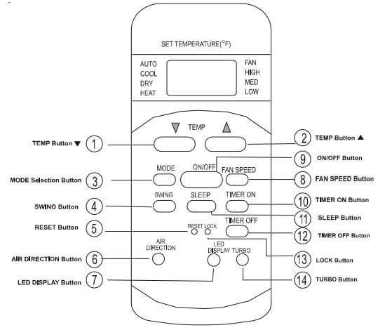
Problem: Unit does not start
Cause:
- Power has been lost
- Unit may be unplugged
- Fuse may have blown
- Battery in remote may be weak
- Incorrect time set in TIMER mode
Solution:
- Wait for power to be restored
- Check that plug is securely in wall receptable
- Replace the fuse
- Replace the battery
- Wait or cancel timer setting
Problem: (Cooling/Heating models only) Unit not cooling or heating space adequately. Air is coming from the unit
Cause:
- Temperature setting is incorrect
- Air Filter is blocked
- Doors or windows are open
- Air inlet/outlet of indoor or outdoor unit may be blocked
- 3 minute compressor protection has been activated
Solution:
- Set temperature correctly. Refer to “Remote Control” section for additional informaiton
- Clean the air filter
- Close doors and windows
- Clear obstructions and restart unit
- Turn off unit. Wait at least 3 minutes and restart unit.
If the problem has not been corrected, please contact your local dealer or the nearest customer service center. Be prepared to tell them specific malfunctions and the unit model.
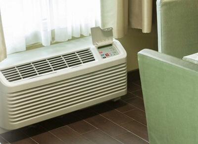
PTAC Codes
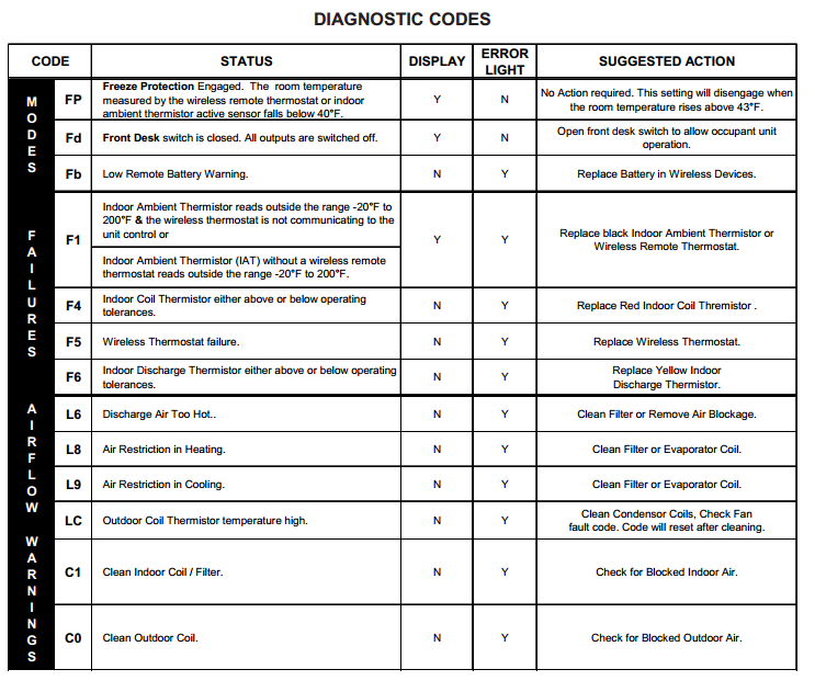
Freeze Protection Engaged. The room temperature measured by the wireless remote thermostat or indoor ambient thermistor active sensor falls below 40°F.
| Error Codes | Meaning |
|---|---|
| FP | Freeze Protection Engaged. The room temperature measured by the wireless remote thermostat or indoor ambient thermistor active sensor falls below 40°F. |
| Fd | Front Desk switch is closed. All outputs are switched off. |
| Eo | Un-Configured Service Board - All operation held awaiting configuration. |
| EH | Emergency Hydronic Engaged. The EHH switch is closed. Compressor is switched off. |
| LS | Load Shedding Engaged. The LS switch is closed. Compressor and Electric heat is switched off. |
| On | Control is configured to respond to a wired thermostat |
| oP | Open Door Lockout (DS1 & DS2 open; wireless) |
| nP | Window Switch Lockout - (LS & INN open) |
| HP | Heat Sentinel - (WIAT > u3) |
| Ur | Un-Rented Status (EHH & INN or wireless) |
| F1 | Indoor Ambient Thermistor reads outside the range -20°F to 200°F & the wireless thermostat is not communicating to the unit control or Indoor Ambient Thermistor (IAT) without a wireless remote thermostat reads outside the range -20°F to 200°F. |
| F2 | Wireless Remote Thermostat failure |
| F3 | Indoor Ambient Thermistor reads outside the range -20°F to 200°F |
| F4 | Indoor Coil Thermistor either above or below operating tolerances. |
| F5 | Wireless Thermostat failure. |
| F6 | Indoor Discharge Thermistor either above or below operating tolerances. |
| Fb | Low Remote Battery Warning. |
| H1 | High Voltage Protection engaged. Power supply voltage is to high. |
| br | Brown Out Protection engaged. Power was lost or voltage is low. |
| L6 | Discharge Air Too Hot |
| LC | Outdoor Coil Thermistor temperature high. |
| C2 | Indoor Air Recirculation. Large delta between thermostat and return. |
| C5 | Outdoor Coil temperature too high for outdoor ambient temperature. |
| C1 | Indoor Coil is freezing up. |
| C3 | Indoor Coil is freezing up. |
| C4 | Indoor Coil froze up. |
| C6 | Poor Unit Performance. |
| C7 | Indoor Freezing Lockout (ICT - IAT > 20) +10 Min |
Digital Board Diagnostics
If a failure is detected on the digital board, there will be a green light constantly lit up. This light is located under the OFF touch pad button. The board will need to enter in the Diagnostic Mode to determine failure code and procedures to follow to correct problem.
Diagnostic Maintenance & Status Report
The Diagnostic Maintenance & Status Report Mode provides detailed information on PTAC control operation and operational status including present modes, failures, airflow restriction warnings, operating temperatures, and past failures. The lower right hand dot on the center display flashes in this mode. In some cases the green LED located in the lower left hand corner of the touchpad below the OFF key will also be lit. This Green LED “Status Light“ only illuminates if there is an status code that has been activated and should be reviewed. In most cases, this light indicates that the indoor room filter is dirty should be cleaned or replaced.
NOTE: Dirty filters cause the unit to consume more energy than normally needed to condition a room. Once the filter has been cleaned or replaced, the LED should go out. If the LED is still illuminated after the filter has been cleaned, activate the Diagnostic and Status mode to view any active codes. The unit may need additional cleaning or maintenance of the evaporator or condenser coils. Please perform this step before calling a servicer. A servicer should be called only if cleaning the filter or coils does not clear the status code or the code indicates that servicer should be called.
From the beginning, every Amana® brand product has been made with the same core philosophy: to provide our customers with high-quality products that are reliable, meet their needs, and last longer than the rest.
And we keep that philosophy firmly in mind as we build our industry-leading Amana brand Packaged Terminal Air Conditioners (PTACs) and air-conditioning and heating products.
Who Is Providing The Warranty?
This warranty is provided to you by Goodman Company, L.P. (“Goodman”), which warrants all parts of this heating or air conditioning unit, as described below.
To What Type Of Installations Does This Warranty Apply?
This warranty applies to heating and air conditioning units installed in buildings other than residences. Different warranties apply to units installed in owner-occupied residences and in residences not occupied by the owner. What
Units Does This Warranty Not Cover?
This warranty does not apply to: Units that are installed outside the United States, its territories, or Canada. Units that are operated in incomplete structures. Units that are installed in residential buildings.
Manual Pdf
Goodman Air Conditioner Manual
Other Post
- Unionaire Air Conditioner Error Codes - December 1, 2025
- Ameristar AC Error Codes and Troubleshooting - December 1, 2025
- Rheem Pool Heat Pump Error Codes - December 1, 2025

I keep getting blower error when blows heat or air conditioning. The error #is b3. What’s causing this it’s been doing it sincere about 5 years now
Hello, had a brand new Goodman heat pump GSZC16036 heat pump and air handler AVPTC37C installed yesterday in FL and unit powered up and ran just fine for a minute, then received error code “A05 FAn” flashing in red. Can’t find anywhere what this code means. Can someone please help me? Thank you in advance!
I have a new variable speed goodman 5ton AC and handler.
Goodman can’t answer the code that is flashing nor can anyone else I’ve talked to.
3green flashes so communicating well then FAn blinks for fan on then blinks AOE? Anyone know what the heck this means?
Hello…
I keep getting an error code on my Goodman A/C unit of L2 or HC01, and the unit fails to run. When I toggle the main circuit breaker for the unit, it comes back on. Any ideas on where the problem is? Thanks.
i Have purchased a 18 seer goodman 3ton last week. Had it installed by installer . I went out checked it the other day . It seemed to be defrosting frequent . So i pulled cover it is showing a A-2 code . book said it is a open outdoor air sensor . Ok now i seen a plug with two black wires not plugged to board , could this be the problem.