
Chilled water inlet and outlet openings are covered for shipment. Each compressor has a separate compressor motor starter. The RTAC series features Trane’s exclusive Adaptive Control ™ logic, which monitors the control variables that govern the operation of the chiller unit.
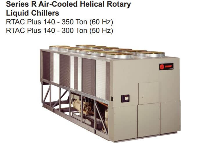
Series R Air-Cooled Helical Rotary Liquid Chillers – RTAC Plus 140 – 350 Ton (60 Hz) RTAC Plus 140 – 300 Ton (50 Hz)
Diagnostics
| Hex Code | Diagnostic Name |
|---|---|
| 398 | BAS Communication Lost. The BAS was setup as “installed” at the MP and the Comm 3 LLID lost communications with the BAS for 15 contiguous minutes after it had been established. Refer to Section on Setpoint Arbitration to determine how setpoints and operating modes may be effected by the comm loss. The chiller follows the value of the Tracer Default Run Command which can be previously written by Tracer and stored nonvolatilely by the MP (either use local or shutdown). |
| 390 | BAS Failed to Establish. The BAS was setup as “installed” and the BAS did not communicate with the MP within 15 minutes after power-up. Refer to Section on Setpoint Arbitration to determine how setpoints and operating modes may be effected. Note: The original requirement for this was 2 minutes, but was implemented at 15 minutes for RTAC |
| 2E6 | Check Clock. The real time clock had detected loss of its oscillator at some time in the past. This diagnostic can be effectively cleared only by writing a new value to the chiller's time clock using the TechView or DynaView's "set chiller time" functions. |
| 8A | Chilled Water Flow (Entering) The entering evaporator water temp fell below the leaving evaporator water temp. by more than 2°F for 100 °F-sec. For RTAC this diagnostic cannot reliably indicate loss of flow, but can warn of improper flow direction through the evaporator, misbound temperature sensors, or other system problems. |
| 5EF | Comm Loss: Chilled Water Flow Switch. Continual loss of communication between the MP and the Immediate Functional ID has occurred for a 30 second period. |
| 5F2 | Comm Loss: Cond Rfgt. Immediate Latch Same as Comm Loss: Chilled Water Flow Switch. |
| 694 | Comm Loss: Electronic Expansion Valve, Circuit #1. Same as Comm Loss: Chilled Water Flow Switch Remote. |
| 695 | Comm Loss: Electronic Expansion Valve, Circuit #2. Same as Comm Loss: Chilled Water Flow Switch Remote. |
| 5DE | Comm Loss: Emergency Stop. Same as Comm Loss: Chilled Water Flow Switch Remote Stop. |
| 68E | Comm Loss: Evap Oil Return Valve, Cprsr 1A. Same as Comm Loss: Chilled Water Flow Switch Remote. |
| 69E | Comm Loss: Evap Oil Return Valve, Cprsr 1B. Same as Comm Loss: Chilled Water Flow Switch. |
| 68F | Comm Loss: Evap Oil Return Valve, Cprsr 2A. Same as Comm Loss: Chilled Water Flow Switch. |
| 69F | Comm Loss: Evap Oil Return Valve, Cprsr 2B. Same as Comm Loss: Chilled Water Flow Switch. |
| 5E4 | Comm Loss: Evaporator Entering Water Temperature. Same as Comm Loss: Chilled Water Flow Switch. |
| 5E3 | Comm Loss: Evaporator Leaving Water Temperature. Same as Comm Loss: Chilled Water Flow Switch. |
| 6BB | Comm Loss: Evaporator Rfgt Drain Valve - Ckt 1. Same as Comm Loss: Chilled Water Flow Switch. |
| 6BC | Comm Loss: Evaporator Rfgt Drain Valve - Ckt 2. Same as Comm Loss: Chilled Water Flow Switch. |
| 688 | Comm Loss: Evaporator Rfgt Liquid Level, Circuit #1. Same as Comm Loss: Chilled Water Flow Switch. |
| 689 | Comm Loss: Evaporator Rfgt Liquid Level, Circuit #2. Same as Comm Loss: Chilled Water Flow Switch. |
| 5F0 | Comm Loss: Evaporator Rfgt Pressure, Circuit #1. Continual loss of communication between the MP and he Functional ID has occurred for a 30 second period. Note: This diagnostic is replaced by diagnostic 5FB below with Rev 15.0. |
| 5F1 | Comm Loss: Evaporator Rfgt Pressure, Circuit #2. Continual loss of communication between the MP and the Functional ID has occurred for a 30 second period. Note: This diagnostic is replaced by diagnostic 5FD below with Rev 15.0. |
| 5F8 | Comm Loss: Evaporator Water Pump Control. Same as Comm Loss: Chilled Water Flow Switch. |
| 5DD | Comm Loss: External Auto/ Stop. Same as Comm Loss: Chilled Water Flow Switch Remote. |
| 5E9 | Comm Loss: External Chilled Water Setpoint. Continual loss of communication between the MP and the Functional ID has occurred for a 30 second period. Chiller shall discontinue use of the External Chilled Water Setpoint source and revert to the next higher priority for setpoint arbitration. |
| 5DF | Comm Loss: External Circuit Lockout, Circuit #1. Continual loss of communication between the MP and the Functional ID has occurred for a 30 second period. MP will nonvolatily hold the lockout state (enabled or disabled) that was in effect at the time of comm loss. |
| 5E0 | Comm Loss: External Circuit Lockout, Circuit #2. Same as Comm Loss: External Circuit Lockout, Circuit #1. |
| 5EA | Comm Loss: External Current Limit Setpoint. Continual loss of communication between the MP and the Functional ID has occurred for a 30 second period. Chiller shall discontinue use of the External Current limit setpoint and revert to the next higher priority for Current Limit setpoint arbitration. |
| 680 | Comm Loss: Fan Control Circuit #1, Stage #1. Same as Comm Loss: Chilled Water Flow Switch. |
| 681 | Comm Loss: Fan Control Circuit #1, Stage #2. Same as Comm Loss: Chilled Water Flow Switch. |
| 682 | Comm Loss: Fan Control Circuit #1, Stage #3. Same as Comm Loss: Chilled Water Flow Switch. |
| 683 | Comm Loss: Fan Control Circuit #1, Stage #4. Same as Comm Loss: Chilled Water Flow Switch. |
| 684 | Comm Loss: Fan Control Circuit #2, Stage #1. Same as Comm Loss: Chilled Water Flow Switch. |
| 685 | Comm Loss: Fan Control Circuit #2, Stage #2. Same as Comm Loss: Chilled Water Flow Switch. |
| 686 | Comm Loss: Fan Control Circuit #2, Stage #3. Same as Comm Loss: Chilled Water Flow Switch. |
| 687 | Comm Loss: Fan Control Circuit #2, Stage #4. Same as Comm Loss: Chilled Water Flow Switch. |
| 68C | Comm Loss: Fan Inverter Fault, Circuit #1 or Circuit #1, Drive 1. Continual loss of communication between the MP and the Functional ID has occurred for a 30 second period. Operate the remaining fans as fixed speed fan deck. |
| 68D | Comm Loss: Fan Inverter Fault, Circuit #1, Drive 2. Same as Comm Loss: Fan Inverter Fault, Circuit #1 or Circuit #1, .Drive 1. |
| 69A | Comm Loss: Fan Inverter Fault, Circuit #2 or Circuit #2. Same as Comm Loss: Fan Inverter Fault, Circuit #1 or Circuit #1, .Drive 1. |
| 69B | Comm Loss: Fan Inverter Fault, Circuit #2, Drive 2. Same as Comm Loss: Fan Inverter Fault, Circuit #1 or Circuit #1, .Drive 1. |
| 68A | Comm Loss: Fan Inverter Power, Circuit #1 or Circuit #1 Drive 1 and 2. Same as Comm Loss: Fan Inverter Fault, Circuit #1 or Circuit #1, .Drive 1. |
| 698 | Comm Loss: Fan Inverter Power, Circuit #2 or Circuit #2 or Drive 1 and 2. Same as Comm Loss: Fan Inverter Fault, Circuit #1 Drive 1. |
| 68B | Comm Loss: Fan Inverter Speed Command, Circuit #1 or Circuit #1 Drive 1 and 2. Same as Comm Loss: Fan Inverter Fault, Circuit #1 or Circuit #1, .Drive 1. |
| 699 | Comm Loss: Fan Inverter or Circuit #2 Drive 1 and 2 Speed Command, Circuit #2. Same as Comm Loss: Fan Inverter Fault, Circuit #1 or Circuit #1,.Drive 1. |
| 5D9 | Comm Loss: Female Step Load Compressor 1A. Same as Comm Loss: Chilled Water Flow Switch. |
| 5DA | Comm Loss: Female Step Load Compressor 1B. |
| 5DB | Comm Loss: Female Step Load Compressor 2A |
| 5DC | Comm Loss: Female Step Load Compressor 2B |
| 5EB | Comm Loss: High Pressure Cutout Switch, Cprsr 1A |
| 5EC | Comm Loss: High Pressure Cutout Switch, Cprsr 1B |
| 5ED | Comm Loss: High Pressure Cutout Switch, Cprsr 2A |
| 5EE | Comm Loss: High Pressure Cutout Switch, Cprsr 2B |
| 5E1 | Comm Loss: Ice-Machine Control |
| 5FA | Comm Loss: Ice-Making Status |
| 5F4 | Comm Loss: Intermediate Oil Pressure, Cprsr 1A |
| 5F5 | Comm Loss: Intermediate Oil Pressure, Cprsr 1B |
| 5F6 | Comm Loss: Intermediate Oil Pressure, Cprsr 2A |
| 5F7 | Comm Loss: Intermediate Oil Pressure, Cprsr 2B |
| 69D | Comm Loss: Local BAS Interface |
| 5D2 | Comm Loss: Male Port Load Compressor 1A |
| 5D4 | Comm Loss: Male Port Load Compressor 1B |
| 5D6 | Comm Loss: Male Port Load Compressor 2A |
| 5D8 | Comm Loss: Male Port Load Compressor 2B |
| 5D1 | Comm Loss: Male Port Unload Compressor 1A |
| 5D3 | Comm Loss: Male Port Unload Compressor 1B |
| 5D5 | Comm Loss: Male Port Unload Compressor 2A |
| 5D7 | Comm Loss: Male Port Unload Compressor 2B |
| 5E5 | Comm Loss: Oil Temperature, Circuit #1 or Cprsr 1A |
| 5E6 | Comm Loss: Oil Temperature, Circuit #2 or Cprsr 2A |
| 696 | Comm Loss: Oil Temperature, Cprsr 1B |
| 697 | Comm Loss: Oil Temperature, Cprsr 2B |
| 5E2 | Comm Loss: Outdoor Air Temperature |
| 690 | Comm Loss: Starter 1A |
| 691 | Comm Loss: Starter 1B |
| 692 | Comm Loss: Starter 2A |
| 693 | Comm Loss: Starter 2B |
| 6AC | Comm Loss: Starter Panel High Temperature Limit – Panel 1, Cprsr 1B |
| 6AB | Comm Loss: Starter Panel High Temperature Limit – Panel 1, Cprsr 2A |
| 6AD | Comm Loss: Starter Panel High Temperature Limit – Panel 2, Cprsr 2B |
| 6A0 | Comm Loss: Status/ Annunciation Relays |
| 5FB | Comm Loss: Suction Pressure Cprsr 1A |
| 5FC | Comm Loss: Suction Pressure Cprsr 1B |
| 5FD | Comm Loss: Suction Pressure Cprsr 2A |
| 5FE | Comm Loss: Suction Pressure Cprsr 2B |
| 2A1 | Condenser Fan Variable Speed Drive Fault – Circuit 1 (Drive 1) |
| 5B4 | Condenser Fan Variable Speed Drive Fault – Circuit 1 Drive 2 |
| 2A2 | Condenser Fan Variable Speed Drive Fault – Circuit 2 (Drive 1) |
| 5B5 | Condenser Fan Variable Speed Drive Fault – Circuit 2 (Drive 2) |
| 5B8 | Condenser Refrigerant Pressure Transducer – Circuit 1 |
| 5B9 | Condenser Refrigerant Pressure Transducer – Circuit 2 |
| FD | Emergency Stop |
| 8E | Evaporator Entering Water Temperature Sensor |
| AB | Evaporator Leaving Water Temperature Sensor |
| 27D | Evaporator Liquid Level Sensor - Circuit 1 |
| 3F9 | Evaporator Liquid Level Sensor - Circuit 2 |
| 6B9 | Evaporator Rfgt Drain - Circuit 1 |
| 6BA | Evaporator Rfgt Drain - Circuit 2 |
| ED | EvaporatorWater Flow Lost |
| 384 | Evaporator Water Flow Overdue |
| 5C4 | Excessive Loss of Comm |
| 87 | External Chilled Water Setpoint |
| 89 | External Current Limit Setpoint |
| 1C6 | High Differential Refrigerant Pressure - Circuit 1 |
| 1C7 | High Differential Refrigerant Pressure - Circuit 2 |
| 584 | High Evaporator Liquid Level - Circuit 1 |
| 5B7 | High Evaporator Liquid Level - Circuit 2 |
| 6B8 | High Evaporator Refrigerant Pressure |
| 1DE | High Oil Temperature - Compressor 1A |
| 1E0 | High Oil Temperature - Compressor 1B |
| 1DD | High Oil Temperature - Compressor 2A |
| 1DF | High Oil Temperature - Compressor 2B |
| F5 | High Pressure Cutout - Compressor 1A |
| F6 | High Pressure Cutout - Compressor 1B |
| BE | High Pressure Cutout – Compressor 2A |
| BF | High Pressure Cutout – Compressor 2B |
| 5BE | Intermediate Oil Pressure Compressor 2A |
| BF | High Pressure Cutout – Compressor 2B |
| 5BE | Intermediate Oil Pressure Transducer - Compressor 1A |
| 5BF | Intermediate Oil Pressure Transducer - Compressor 1B |
| 5C0 | Intermediate Oil Pressure Transducer - Compressor 2A |
| 5C1 | Intermediate Oil Pressure Transducer - Compressor 2B |
| C5 | Low Chilled Water Temp: Unit Off |
| C6 | Low Chilled Water Temp: Unit On |
| 1AE | Low Differential Refrigerant Pressure - Circuit 1 |
| 1AF | Low Differential Refrigerant Pressure - Circuit 2 |
| 583 | Low Evaporator Liquid Level - Circuit 1 |
| 5B6 | Low Evaporator Liquid Level - Circuit 2 |
| 194 | Low Evaporator Refrigerant Temperature - Circuit 1 |
| 195 | Low Evaporator Refrigerant Temperature - Circuit 2 |
| 6B3 | Low Evaporator Temp – Ckt 1: Unit Off |
| 6B3 | Low Evaporator Temp – Ckt 2: Unit Off |
| 198 | Low Oil Flow – Compressor 1A |
| 199 | Low Oil Flow – Compressor 1B |
| 19A | Low Oil Flow – Compressor 2A |
| 19B | Low Oil Flow – Compressor |
| B5 | Low Suction Refrigerant Pressure - Circuit 1 |
| B6 | Low Suction Refrigerant Pressure - Circuit 2 |
| B7 | Low Suction Refrigerant Pressure - Cprsr 1B |
| B8 | Low Suction Refrigerant Pressure - Cprsr 2B |
| BA | Motor Current Overload – Compressor 1A |
| BB | Motor Current Overload – Compressor 1B |
| BC | Motor Current Overload – Compressor 2A |
| BD | Motor Current Overload – Compressor 2B |
| 1AD | MP Application Memory CRC Error |
| 6A1 | MP: Could not Store Starts and Hours |
| 5FF | MP: Invalid Configuration |
| 6A2 | MP: Non-Volatile Block Test Error |
| 69C | MP: Non-Volatile Memory Reformat |
| D9 | MP: Reset Has Occurred |
| 1E1 | Oil Flow Fault – Compressor 1A |
| 1E2 | Oil Flow Fault – Compressor 1B |
| 5A0 | Oil Flow Fault – Compressor 2A |
| 5A1 | Oil Flow Fault – Compressor 2B |
| 1E6 | Oil Temperature Sensor – Cprsr 1B |
| 1E8 | Oil Temperature Sensor – Cprsr 2B |
| 1E6 | Oil Temperature Sensor – Cprsr 1A |
| 1E8 | Oil Temperature Sensor – Cprsr 2B |
| 1E6 | Oil Temperature Sensor – Cprsr 1A |
| 1E7 | Oil Temperature Sensor – Cprsr 2A |
| A1 | Outdoor Air Temperature Sensor |
| D7 | Over Voltage |
| 19C | Phase Loss – Compressor 1A |
| 19D | Phase Loss - Compressor 1B |
| 19E | Phase Loss - Compressor 2A |
| 19F | Phase Loss - Compressor 2B |
| 184 | Phase Reversal – Compressor 1A |
| 185 | Phase Reversal – Compressor 1B |
| 186 | Phase Reversal – Compressor 2A |
| 187 | Phase Reversal – Compressor 2B |
| 1A0 | Power Loss – Compressor 1A |
| 1A1 | Power Loss - Compressor 1B |
| 1A2 | Power Loss - Compressor 2A |
| 1A3 | Power Loss - Compressor 2B |
| 8C | Pumpdown Terminated – Circuit 1 |
| 8D | Pumpdown Terminated – Circuit 2 |
| 1B2 | Severe Current Imbalance – Compressor 1A |
| 1B3 | Severe Current Imbalance – Compressor 1B |
| 1B4 | Severe Current Imbalance – Compressor 2A |
| 1B5 | Severe Current Imbalance – Compressor 2B |
| 5CD | Starter 1A Comm Loss: MP |
| 6A7 | Starter 1A Dry Run Test |
| 5CE | Starter 1B Comm Loss: MP |
| 6A8 | Starter 1B Dry Run Test |
| 5CF | Starter 2A Comm Loss: MP |
| 6A9 | Starter 2A Dry Run Test |
| 5D0 | Starter 2B Comm Loss: MP |
| 6AA | Starter 2B Dry Run Test |
| CC | Starter Contactor Interrupt Failure - Compressor 2A |
| CA | Starter Contactor Interrupt Failure - Compressor 1A |
| CB | Starter Contactor Interrupt Failure - Compressor 1B |
| CD | Starter Contactor Interrupt Failure - Compressor 2B |
| 180 | Starter Did Not Transition – Compressor 1A |
| 181 | Starter Did Not Transition – Compressor 1B |
| 182 | Starter Did Not Transition – Compressor 2A |
| 183 | Starter Did Not Transition – Compressor 2B |
| 6A3 | Starter Failed to Arm/Start – Cprsr 1A |
| 6A4 | Starter Failed to Arm/Start – Cprsr 1B |
| 6A5 | Starter Failed to Arm/Start – Cprsr 2A |
| 6A6 | Starter Failed to Arm/Start – Cprsr 2B |
| 1E9 | Starter Fault Type I – Compressor 1A |
| 1 EA | Starter Fault Type I – Compressor 1B |
| 1 EB | Starter Fault Type I – Compressor 2A |
| 1EC | Starter Fault Type I – Compressor 2B |
| 1ED | Starter Fault Type II – Compressor 1A |
| 1EE | Starter Fault Type II – Compressor 1B |
| 1EF | Starter Fault Type II – Compressor 2A |
| 1F0 | Starter Fault Type II – Compressor 2B |
| 1F1 | Starter Fault Type III – Compressor 1A |
| 1F2 | Starter Fault Type III – Compressor 1B |
| 1F3 | Starter Fault Type III – Compressor 2A |
| 1F4 | Starter Fault Type III – Compressor 2B |
| 5C7 | Starter Module Memory Error Type 1 - Starter 2A |
| 5C8 | Starter Module Memory Error Type 1 - Starter 2B |
| 5C5 | Starter Module Memory Error Type 1Starter 1A |
| 5C6 | Starter Module Memory Error Type 1-Starter 1B |
| 5C9 | Starter Module Memory Error Type 2 - Starter 1A |
| 5CA | Starter Module Memory Error Type 2 - Starter 1B |
| 5CB | Starter Module Memory Error Type 2 - Starter 2A |
| 5CC | Starter Module Memory Error Type 2 - Starter 2B |
| 6B1 | Starter Panel High Temperature Limit – Panel 1, Cprsr 1B |
| 6B0 | Starter Panel High Temperature Limit – Panel 1, Cprsr 2A |
| 6B2 | Starter Panel High Temperature Limit – Panel 2, Cprsr 2B |
| 5BA | Suction Refrigerant Pressure Transducer – Circuit 1, Compressor 1A |
| 5BB | Suction Refrigerant Pressure Transducer – Circuit 1, Compressor 1B |
| 5BC | Suction Refrigerant Pressure Transducer - Circuit 2, Compressor 2A |
| 5BD | Suction Refrigerant Pressure Transducer - Circuit 2, Compressor 2B |
| 5B0 | Transition Complete Input Opened - Compressor 1A |
| 5B1 | Transition Complete Input Opened - Compressor 1B |
| 5B2 | Transition Complete Input Opened - Compressor 2A |
| 5B3 | Transition Complete Input Opened - Compressor 2B |
| 5AC | Transition Complete Input Shorted - Compressor 1A |
| 5AD | Transition Complete Input Shorted - Compressor 1B |
| 5AE | Transition Complete Input Shorted - Compressor 2A |
| 5AF | Transition Complete Input Shorted - Compressor 2B |
| D8 | Under Voltage |
| 771 | Very Low Evaporator Refrigerant Pressure – Circuit 1 |
| 772 | Very Low Evaporator Refrigerant Pressure – Circuit 2 |
Manual Pdf
Series R Air-Cooled Helical Rotary Liquid Chillers Manual PDF
RTAC Air-Cooled Helical Rotary Liquid Chillers PDF
Air-Cooled Scroll Chillers Model CGAM 20 – 130 Tons Installation Operation Maintenance

HVAC Expert at acerrorcode.com
Regarding error and fault codes, we believe sharing knowledge is the best way to help everyone. That is why we established ACErrorCode.com, to give you every bit of info you need as a customer. HVAC Expert Contact: dannyreese@acerrorcode.com
Latest posts by Danny Reese (see all)
- Unionaire Air Conditioner Error Codes - December 1, 2025
- Ameristar AC Error Codes and Troubleshooting - December 1, 2025
- Rheem Pool Heat Pump Error Codes - December 1, 2025
Thank you for the information.
i have chierl trane ,air cooled alarm evap water flow (entering water temp)
I have RTAC275 chiller, give me alarm, Phase loss. Cprsr 1A – Phase loss – Cprsr 1B, can you help me?
hi I av a Trane chiller,whats the problem means with E3,,Am bhupen from kenya
Low Oil Flow – Compressor 2A
Low Oil Flow – Compressor 2B
Oil Flow Fault – Compressor 2A
Oil Flow Fault – Compressor 2B
Starter Failed to Arm/Start – Cprsr 2A