York International started in 1874, is a York Pennsylvania-based company that develops HVAC equipment and refrigeration equipment. The company started an independent venture, but in 2005 was purchased by Johnson Controls. Selling at a whopping $3.2 billion US dollars the company was back then the world’s largest independent manufacturer of heating, air conditioning, and refrigeration machinery. Making it a wonderful purchase for Johnsons Controls, which has since then risen to great heights.
Johnsons Controls on the other hand is a multinational conglomerate with headquarters in Cork, Ireland. Even though the company is based at a great distance from York, Pennsylvania it does not stop it from offering its products to local markets all around the world.
When facing an error code we suggest you grab a pen and paper to note down the code rather than pressing various buttons on your York VRF. This way you will not risk damaging your appliance any further and will be able to find out the exact issue using the common error code list for York VRF error codes listed below. Once you nail down the issue you can easily call in a professional, or fix the issue yourself.
Malfunction and Protection Codes Table
Malfunction and Protection Code Table. The display board in digital scroll system is just to display running conditions and malfunction information. The manual button is just to check the address code and power code of indoor units.
| Error Codes | Contents |
|---|---|
| E0 | Phase sequence or lack of phase |
| E1 | Communication malfunction |
| E2 | T1 sensor malfunction |
| E3 | T2A sensor malfunction |
| E4 | T2B sensor malfunction |
| E5 | T3 sensor malfunction |
| E6 | Over-zero checking malfunction |
| E7 | EEPROM malfunction |
| E8 | Fan motor checking out of control |
| E9 | Communication malfunction between PCB and Display board |
| EF | Other malfunction |
| EE | Water level checking malfunction |
| ED | Outdoor protection |
| EC | Clear malfunction |
| EB | Inverter Module Protection |
| EA | Compressor Over-current (4 times) |
| P0 | Evaporator Temp. Protection |
| P1 | Anti-cooling or Defrost Protection |
| P2 | Condenser High Temp. Protection |
| P3 | Compressor Temp. Protection |
| P4 | Discharge Pipe Temp. Protection |
| P5 | Discharge High-pressure Protection |
| P6 | Discharge Low-pressure Protection |
| P7 | Power Lack/Over Volt Protection |
| P8 | Compressor Over-current |
| PF | Other Protection |
| PE | Oil Balance |
| PD | Oil Return |
| H1 | Net communication malfunction |
| H2 | Outdoor decreasing malfunction (valid for host unit) |
| H3 | Outdoor adding malfunction (valid for host unit) |
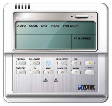
Troubleshooting
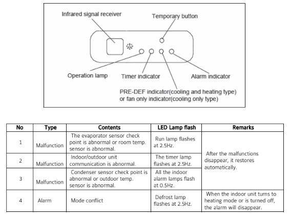
The air-conditioner does not run after pressing ON/OFF button.
Communication malfunction between outdoor units (Only valid for 20,30HP)
Display: The outdoor unit digital diode is displaying “E0”
Solutions:
- Check if communication cable is broken off
- Exchange P, Q line if there is no broken circuit
Phase sequence error
Display: The outdoor unit digital diode is displaying “E1”
Solutions:
- Check if the voltage between the power line terminals A, B, C of outdoor units and N is normally 220v. If not please check whether the power lines are well connected.
- After checking the voltage without finding any error, please transpose any two of the outdoor units power lines (A, B.C.)
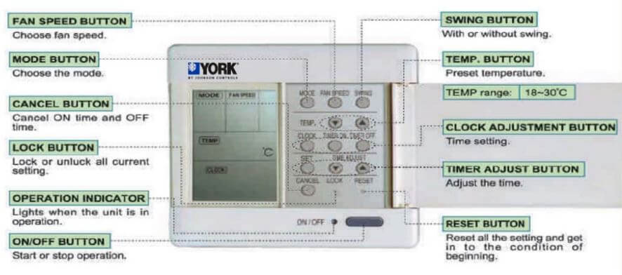
Communication trouble between indoor unit and outdoor unit
Display: Outdoor unit digital diode is displaying “E2” and the timer lamp on the display board of the indoor unit, which has the communication trouble blinks.
Solutions:
- Check if communication cable is broken off
- Exchange P, Q line if there is no broken circuit
Outdoor unit temperature sensor abnormal
Display: Outdoor unit digital diode is displaying E3, E4, E5, and E7 (Only valid for 20,30HP)
Solutions:
- Measure T3, T4, T5, T6 electric resistance respectively and replace the broken one if the electric resistance is not correct.
- If the electric resistance is normal, please test the outdoor PCB and change a new one if it does not work well.
Indoor unit temperature sensor abnormal
Display: The operation lamp of the indoor unit blinks
Solutions:
- Measure T1, T2, and T3 electric resistance respectively to see if there is an open or short circuit
- If the electric resistance is normal, please test the indoor PCB and change a new one if it does not work well.
Water-level switch abnormal
Display: Outdoor unit digital diode display “E6” and Indoor unit alarm lamp blinks
Method: Check if the water level switch is closed and replace a new switch if the old one is bad.
The address of outdoor unit malfunction (Only valid for 20,30HP)
Display: Outdoor unit digital diode display “E8”
Method: Check the address code of outdoor unit PCB and make sure the address code in the right position
After running a while the system stops to perform protection.
Water level alarming trouble
Display: Indoor unit alarm lamp blinks
Solutions:
- Check if water pump runs well
- Check if the drainpipe is broken
- Check if the water level switch is blocked
- If the above situations do not occur please change a new indoor PCB
High-pressure protection
Display: The outdoor unit digital diode is displaying:”P1”
Solutions:
- Check if the high-pressure protection switch is broken or loosen
- Test if the discharge temperature of the compressor is too high. If the discharge temperature is too high and the current is lower than the rated current, the system is probably lack of refrigerant and replenishes it.
- Test if the pressure (high pressure) is too high or the current is overloaded. If so the possible causes are: the overcharge of refrigerant, the system air leakage, or bad ventilation conditions.
Low-pressure protection
Display: The outdoor unit digital diode is displaying:”P2”
Solutions:
- Check if the low pressure protection switch is broken or loosen
- Test if the pressure (low pressure) is too low. The probable reasons are: the overcharge of refrigerant or system blockade.
Over current protection
Display: The outdoor unit diode. Is displaying:”P3”
Solutions:
- Check if the current is overloaded.
- The possible reasons for the over current are: the overcharge of refrigerant, air leakage, and bad ventilation and heat-emission conditions.
Compressor discharge temperature protection, Condenser high temperature protection
Display: P4/ P5 is displayed on the outdoor unit diode
Solutions:
- Test digital discharge temperature, outdoor condenser T3 temperature
- Test system pressure
- High digital discharge temperature is likely owing to the lack of refrigerant, air leakage or system blockade. Check the above items respectively to solve the problem.
- Condenser high temperature protection owes to the overcharge of refrigerant, air leakage or bad ventilation and heat-emission conditions.
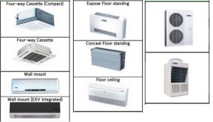
Chiller Codes and Solutions
Real Time Error Numbers
| Error | Description |
|---|---|
| 0 | All Ok |
| 1 | Datum Type Ok Test Failed |
| 2 | English Text Too Long |
| 3 | Floating Point Exception |
| 4 | Get Packet Failed |
| 5 | Get Type Failed |
| 6 | Invalid Unit Conversion |
| 7 | Invalid Hardware Selection |
| 8 | Real Time Fault |
| 9 | Spanish Text Too Long |
| 10 | Thread Exited |
| 11 | Thread Failed |
| 12 | Thread Stalled |
| 13 | Io Board Reset |
| 14 | Bram Invalid |
| 15 | Bacnet Setup Failed |
Problem: No display on panel – unit will not start
Possible Cause:
- Main supply to control system OFF.
- Emergency stop device off.
- CB3 tripped.
- No supply to – T2
- No 24VAC supply to power board.
- No +12V output from powerboard.
Action:
- Switch on main supply if safe to do so.
- Check if control panel emergency stop switch and any remote emergency stop devices are in the OFF position. Turn to ON position (1) if safe to do so.
- Check CB3
- Check 115VAC to L & 2.
- Check wiring from – T2 to powerboard and fuse.
- Replace powerboard or isolate excessive load on the board.
Problem: NO RUN PERM displayed (No run permissive)
Possible Cause:
- No liquid fl ow through the evaporator
- Flow switch or cycling contacts are not made
Action:
- Ensure that liquid pumps are running. Valves are correctly set and fl ow is established.
- Check that the fl ow switch is functional and is installed according to the manufacturer’s instructions. Check cycling contacts.
Problem: SYS # HIGH OIL TEMP
Possible Cause:
- Poor airfl ow through the condenser coils
- Measured temperature incorrect
Action:
- Check for airfl ow restrictions caused by blockages on intake faces of air coils.
- Check oil temp sensor and wiring.
Problem: Chiller FAULT: LOW AMBIENT TEMP displayed
Possible Cause:
- Ambient air temperature is lower than the programmed operating limit.
- Ambient air temperature is lower than the programmed operating limit.
- Measured temperature is incorrect.
Action:
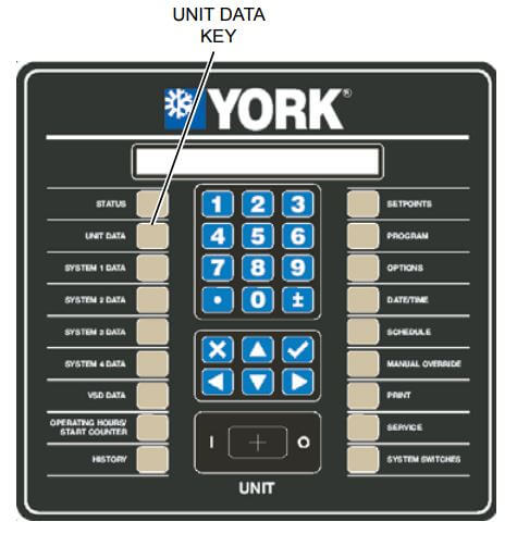
- Use the ‘ambient temp.’ key to display the temperature and confi rm that the displayed value is approximately correct. The warning message should clear when the ambient air temperature rises above the programmed operating limit
- Check the programmed settings are correct for the options fi tted to the unit
- Check ambient sensor and wiring
Problem: Chiller FAULT: HIGH AMBIENT TEMP displayed
Possible Cause:
- Ambient air temperature is higher than the programmed operating limit.
- Ambient air temperature is higher than the programmed operating limit.
- Recirculated air is affecting the sensor
- Measured temperature is incorrect
Action:
- Use the ‘ambient temp.’ key to display the temperature and confi rm that the displayed value is approximately correct. The warning message should clear when the ambient air temperature falls below the programmed operating limit.
- Check that the programmed settings are correct for the options fi tted to the unit.
- Check fans are operating correctly and the rotation is correct. Check for airfl ow recirculation.
- Check ambient sensor and wiring.
Problem: Chiller FAULT: LOW WATER TEMP displayed
Possible Cause:
- Leaving liquid drops below the programmed low limit faster than the unit can unload.
- Unit is not unloading.
- Measured temperature is incorrect.
Action:
- Check for restrictions in the liquid fl ow line. Check that the liquid fl ow is stable.
- Check the voltage to the unloader valve solenoid. Check that the compressor unloads correctly.
- Check water temp sensor and wiring.
Problem: Chiller FAULT: VAC UNDERVOLTAGE displayed.
Possible Cause:
- Poor main supply voltage.
Action:
- Check main supply is stable and within allowable limits.
- Check for voltage dip on compressor start.
Problem: SYS # HIGH DSCH displayed (High discharge pressure trip)
Possible Cause:
- Poor airfl ow through condenser coils.
- Excessive refrigerant charge.
- Measured pressure is incorrect.
Action:
- Check for airfl ow restrictions caused by blockages on intake faces of air coils. Check for damaged fi ns/return bends. Check for correct fan operation and direction of rotation. Check for non-condensables (air) in system.
- Check that the sub-cooling is correct.
- Check discharge transducer and wiring.
Problem: SYS # HIGH DSCH TEMP displayed (High discharge temperature)
Possible Cause:
- Suction superheat too high.
- Poor airfl ow through the condenser coils.
- Measured temperature incorrect.
Action:
- Check suction superheat is within range.
- Check for airfl ow restrictions caused by blockages on intake faces of air coils.
- Check discharge sensor calibration, location and wiring.
Problem: SYS # DSCH LIMITING displayed (Discharge pressure unloading)
Possible Cause: Discharge pressure unloading due to unit operating above load limit. See also SYS # HIGH DSCH.
Action: Check chilled liquid temperature is within range. Check fan operation. Check if ambient air temperature is above design conditions. Check programmed unload point.
Problem: SYS # HIGH OIL PRESS DIFF is displyed. (High oil differential pressure.)
Possible Cause:
- Ball valve in oil circuit closed.
- Dirty / blocked oil fi lter
Action:
- Check ball valves are open position.
- Check and change oil fi lter cartridge.
Problem: SYS # LOW SUCTION displayed
Possible Cause:
- Badly adjusted or faulty expansion valve.
- Reduced evaporator performance.
- Low refrigerant charge.
- Restricted refrigerant flow.
- Measured pressure incorrect.
Action:
- Check superheat.
- Check for restricted chilled liquid flow. Check for fouled tube surfaces. Check superheat.
- Check subcooling is correct. Check for leaks.
- Check for blocked fi lter / drier. Check LLSV is opening correctly.
- Check suction pressure transducer and wiring.
Problem: SYS # LOW CURR/MP/HP displayed
Possible Cause:
- Compressor current too low.
- Measured current is incorrect.
- Compressor motor protector signal failure.
- Mechanical high pressure cut-out trip.
- No motor cooling.
Action:
- Check the compressor main supply voltage, fuses, contactors and wiring. Check main supply voltage is within tolerance. Check 2ACE MP fault code.
- Check for defective Motor Protector Module.
- Check motor protector and wiring.
- Check compressor discharge valve is open. Check cut-out and wiring.
- Check superheat. Check operation of economizer, TXV, and liquid solenoid valve.
Problem: SYS # CURR LIMITING displayed (Compressor current unloading.)
Possible Cause: High compressor motor current has activated unloading.
Action: Check if liquid temperature is within operating limits. Check if ambient air temperature is above operating limits.
Manuals
- Unionaire Air Conditioner Error Codes - December 1, 2025
- Ameristar AC Error Codes and Troubleshooting - December 1, 2025
- Rheem Pool Heat Pump Error Codes - December 1, 2025

on my thermostat I have an error code reading 51 VRF System york type..
York VRF ac why alarms like a key sign?
please I want to learn how to set dip switch in york outdoor pcb.
Hi Ninson,
I would recommend reaching out to the technical service of the device. I hope this issue gets resolved quickly and your ac works smoothly again. If you have any questions or need further assistance, please let me know.
On my thermostats I have an error code reading E30. I have a York VRF system. I believe it’s a communication problem.