Hisense is a multinational white goods and electronics manufacturer based in China. It is the largest television manufacturer in China since 2004, yet offers a wide range of other electrons and appliances as well. Offering its products under a range of brands such as Sharp, Toshiba, Hisense, Ronshen, Kelon, and Gorenje. While the brand name may vary, the products are designed and manufactured by Hisense.
Apart from TVs, the second focus Hisense has is on air conditioning units. These units are available for home and office use, and can easily match your requirements. With a wide range of selections, you cannot go wrong with the one that compliments your space. However, like any other electronic appliance, Hisense ACs are open to errors and issues. Fortunately, most of them are minor and easily fixable.
To help you out we have listed down some of the most common error codes for Hisense ACs. Start by noting down the error code, and match it using the list below. Once you have the error code you can easily find out which area of your air conditioner is acting up, and how to best deal with the situation at hand. Rather than letting someone poke through the system, you can ensure a quick and easy fix.
Codes List
Press the high power for 4 times in a row and the trouble codes listed below will be displayed.
0: No trouble.
1: Outdoor coil temperature sensor in trouble.
2: Compressor temperature sensor in trouble.
3: Voltage transformer in trouble.
4: Current transformer in trouble.
5: IPM module protection.
6: Over and under-voltage control.
7: Communication trouble.
8: Current overload control.
9: Maximum current control.
10: Communication trouble (between outdoor unit and driver unit).
11: Outdoor EEPROM in trouble.
13: Compressor exhaust temperature too high control.
14: Outdoor ambient temperature sensor in trouble.
15: Compressor housing temperature control.
16: Anti-freeze or overload control.
18: DC compressor fails to start.
19: DC compressor out of step.
33: Room temperature sensor in trouble.
34: Indoor coil temperature sensor in trouble.
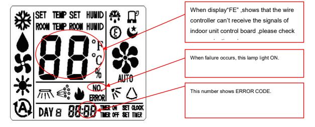
35: Between wire remote controller and indoor unit communication trouble.
36: Communication between the indoor and outdoor in trouble.
37: Water overbrimmed the pump.
38: Indoor EEPROM in trouble.
39: Indoor fan motor operation abnormal.
40: Grid protection alarm (cabinet type).
41: Detecting failures by zero-crossing.
F0: Wire remote controller EEPROM failure. Change wire remote controller.
F1: Wire remote controller temperature sensor failure. Change wire remote controller.
F2: Wire remote controller clock IC failure. Change wire remote controller.
F3: Wire remote controller humidity sensor failure. Change wire remote controller.
FE: Communication between main control board & Wiring remote controller Fault (display on wiring remote controller).
ER: Communication between main control board &display board Fault.
E2: When the evaporator pipe temperature is higher than 63C, the error code will display.
E4: When the indoor fan speed is lower than 200 rpm, the error code will display. There are something block the indoor fan motor.
EA: The error code will display when the communication between display board and control board have in trouble. The connection between the display board and control board is loose.
Display of Codes
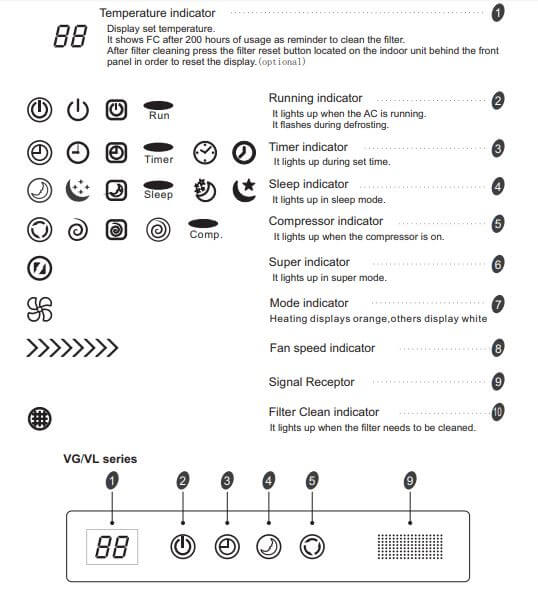
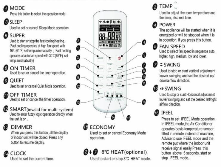
When the system stops running,press the “CHECK” and “↑↓” buttons, “SERVICE” and “00” will display,”00” is index ,press “∧”and “∨” button to set the value, the index value is displayed at the timer area .Each index value shows corresponding content,as follows:
| Codes | Possible Cause |
|---|---|
| 0 | No trouble |
| 1 | Outdoor coil temperature sensor in trouble. 1. Outdoor coil temperature sensor is failure. 2. Outdoor control board in trouble. |
| 2 | Compressor discharge temperature sensor in trouble. 1. Compressor discharge sensor is failure. 2. Outdoor control board in trouble. |
| 5 | IPM protection. 1. Normal protection. 2. Outdoor IPM control board is failure in the outdoor control board. 3. The compressor is failure. |
| 6 | Over and under-voltage control. 1. Voltage of power supply is abnormal. 2. Outdoor control board in trouble. |
| 8 | Current overload control. 1. Normal protection. 2. The outdoor control board in trouble. |
| 9 | Maximum current control. 1. Normal protection. 2. The compressor is failure. |
| 11 | Outdoor EEPROM in trouble. Outdoor control board in trouble. |
| 13 | Compressor exhaust temperature too high control. 1. Heat exchanger and indoor filter were dirty. 2. The refrigeration system was stopt. 3. Compressor discharge temperature sensor is failure. |
| 14 | Outdoor ambient temperature sensor in trouble. 1. Outdoor ambient temperature sensor is failure. 2. Outdoor control board in trouble. |
| 15 | Compressor housing temperature protection. 1. Compressor overheat protection sensor is failure. 2. Outdoor control board in trouble. |
| 16 | Anti-freeze or overload control. 1. Indoor coil temperature sensor is failure. 2. Indoor control board in trouble. |
| 18 | Compressor fails to start. 1. Compressor is failture. 2. Outdoor IPM control board is failure in the outdoor control board. |
| 33 | Room temperature sensor in trouble. 1. Room temperature sensor is failure. 2. Indoor control board in trouble. |
| 34 | Indoor coil temperature sensor in trouble. 1. Indoor coil temperature sensor is failure. 2.Indoor control board in trouble. |
| 35 | Between wire remote controller and indoor unit communication trouble. 1. Wire remote controller in trouble. 2.Indoor control board in trouble. |
| 36 | Communication between the indoor and outdoor in trouble. 1. Connection cable isn’t well connect. 2. Indoor control board in trouble. 3. Outdoor control board in trouble. |
| 37 | Water overbrimmed the pump. Check the pump. |
| 38 | Indoor EEPROM in trouble. Indoor control board in trouble. |
Remote Control
Indication on the Indoor Unit
If the compressor fails when it is interrupted, the indoor unit’s LED flashes indicating the specific trouble code. It flashes as many times as the number of the trouble code is.
| Times | Possible Cause |
|---|---|
| 1 | Outdoor coil temperature sensor in trouble. 1. Outdoor coil temperature sensor is failure. 2. Outdoor control board in trouble. |
| 2 | Compressor discharge temperature sensor in trouble. 1. Compressor discharge sensor is failure. 2. Outdoor control board in trouble. |
| 4 | Current transformer in trouble. |
| 5 | IPM protection. 1. Normal protection. 2. Outdoor IPM control board is failure in the outdoor control board. 3. The compressor is failure. |
| 6 | Over and under-voltage control. 1. Voltage of power supply is abnormal. 2. Outdoor control board in trouble. |
| 8 | Current overload control. 1. Normal protection. 2. The outdoor control board in trouble. |
| 9 | Maximum current control. 1. Normal protection. 2. The compressor is failure. |
| 11 | Outdoor EEPROM in trouble. Outdoor control board in trouble. |
| 13 | Compressor exhaust temperature too high control. 1. Heat exchanger and indoor filter were dirty. 2. The refrigeration system was stopt. 3. Compressor discharge temperature sensor is failure. |
| 14 | Outdoor ambient temperature sensor in trouble. 1. Outdoor ambient temperature sensor is failure. 2. Outdoor control board in trouble. |
| 15 | Compressor housing temperature protection. 1. Compressor overheat protection sensor is failure. 2. Outdoor control board in trouble. |
| 16 | Anti-freeze or overload control. 1. Indoor coil temperature sensor is failure. 2. Indoor control board in trouble. |
| 18 | Compressor fails to start. 1. Compressor is failture. 2. Outdoor IPM control board is failure in the outdoor control board. |
| 33 | Room temperature sensor in trouble. 1. Room temperature sensor is failure. 2. Indoor control board in trouble. |
| 34 | Indoor coil temperature sensor in trouble. 1. Indoor coil temperature sensor is failure. 2. Indoor control board in trouble. |
| 35 | Between wire remote controller and indoor unit communication trouble. 1. Wire remote controller in trouble. 2. Indoor control board in trouble. |
| 36 | Communication between the indoor and outdoor in trouble. 1. Connection cable isn’t well connect. 2. Indoor control board in trouble. 3. Outdoor control board in trouble. |
| 37 | Water overbrimmed the pump. Check the pump. |
| 38 | Indoor EEPROM in trouble. Indoor control board in trouble. |
Portable AC Codes
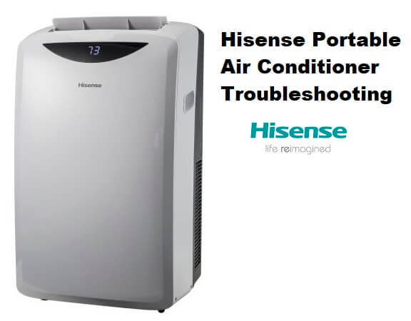
Before calling for service, please try the suggestions below.
Display codes
- If the unit displays error code E5, the water container is full. Drain the water, see “Draining the air conditioner”. After draining, the unit can be operated again.
- P3: High temperature protection of ambient temperature sensor in cooling mode. When the ambient temperature is higher than 65°C, the system displays P3 protection and all units stop running. When the ambient temperature returns drops below 58°C, P3 is removed and normal operation resumes.
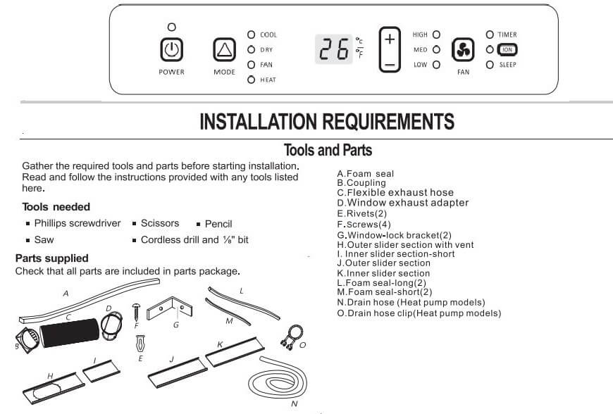
Portable AC Remote Control
VRF Air Conditioner Codes
Inverter-driven Multi-split Air Conditioner (Heat Pump):
| Error Codes | Problem |
|---|---|
| 01 | Activation of Protection Device (Float Switch). Activation of Float Switch. |
| 02 | Activation of Protection Device (High Pressure Cut). Activation of PSH. |
| 03 | Abnormality between Indoor and Outdoor. Incorrect Wiring, Loose Terminals, Disconnect Wire, Blowout of Fuse, Outdoor Unit Power OFF. |
| 04 | Abnormality between Inverter PCB and Outdoor PCB. Inverter PCB - Outdoor PCB Transmission Failure. |
| 05 | Abnormality Power Source Phases. Incorrect Power Source, Connection to Reversed Phase, Open-Phase. |
| 06 | Abnormal Inverter Voltage. Outdoor Voltage Drop, Insufficient Power Capacity. |
| 07 | Decrease in Discharge Gas Superheat. Excessive Refrigerant Charge, Failure of Thermistor, Incorrect Wiring, Incorrect Piping Connection, Expansion Valve Locking at Opened Position (Disconnect Connector). |
| 08 | Increase in Discharge Gas Temperature. Insufficient Refrigerant Charge, Pipe Clogging, Failure of Thermistor, Incorrect Wiring, Incorrect Piping Connection, Expansion Valve Locking at Closed Position (Disconnect Connector). |
| 0A | Abnormality between Outdoor and Outdoor. Incorrect Wiring, Breaking Wire, Loose Terminals. |
| 0b | Incorrect Outdoor Unit Address Setting. Duplication of Address Setting for Outdoor Units (Sub Units) in Same Refrigerant Cycle System. |
| 0C | Incorrect Outdoor Unit Main Unit Setting. Two (or more) Outdoor Units Set as “Main Unit” Exist in Same Refrigerant Cycle System. |
| 11 | Inlet Air Thermistor. Incorrect Wiring, Disconnecting Wiring Breaking Wire, Short Circuit. |
| 12 | Outlet Air Thermistor. Incorrect Wiring, Disconnecting Wiring Breaking Wire, Short Circuit. |
| 13 | Freeze Protection Thermistor. Incorrect Wiring, Disconnecting Wiring Breaking Wire, Short Circuit. |
| 14 | Gas Piping Thermistor. Incorrect Wiring, Disconnecting Wiring Breaking Wire, Short Circuit. |
| 19 | Activation of Protection Device for Indoor Fan. Fan Motor Overheat, Locking. |
| 21 | High Pressure Sensor. Incorrect Wiring, Disconnecting Wiring Breaking Wire, Short Circuit. |
| 22 | Outdoor Air Thermistor. Incorrect Wiring, Disconnecting Wiring Breaking Wire, Short Circuit. |
| 23 | Discharge Gas Thermistor on Top of Compressor. Incorrect Wiring, Disconnecting Wiring Breaking Wire, Short Circuit. |
| 24 | Heat Exchanger Liquid Pipe Thermistor. Incorrect Wiring, Disconnecting Wiring Breaking Wire, Short Circuit. |
| 25 | Heat Exchanger Gas Pipe Thermistor. Incorrect Wiring, Disconnecting Wiring Breaking Wire, Short Circuit. |
| 29 | Low Pressure Sensor. Incorrect Wiring, Disconnecting Wiring Breaking Wire, Short Circuit. |
| 31 | Incorrect Capacity Setting of Outdoor Unit and Indoor Unit. Incorrect Capacity Code Setting of Combination Excessive or Insufficient Indoor Unit Total Capacity Code. |
| 35 | Incorrect Setting of Indoor Unit No. Duplication of Indoor Unit No. in same Ref. Gr. |
| 36 | Incorrect of Indoor Unit Combination. Indoor Unit is Designed for R22. |
| 38 | Abnormality of Picking up Circuit for Protection in Outdoor Unit. Failure of Protection Detecting Device (Incorrect Wiring of Outdoor PCB) |
| 39 | Abnormality Running Current at Constant Speed Compressor. Overcurrent, Blowout Fuse, Current Sensor Failure, Instantaneous Power Failure, Voltage Drop, Abnormal Power Supply. |
| 3A | Abnormality of Outdoor Unit Capacity. Outdoor Unit Capacity > 1350KBtu/h. |
| 3b | Incorrect Setting of Outdoor Unit Models Combination or Voltage. Incorrect Setting of Main and Sub Unit(s) Combination or Voltage. |
| 3d | Abnormality Transmission between Main Unit and Sub Unit(s). Incorrect Wiring, Disconnect Wire, Breaking Wire, PCB Failure. |
| 43 | Activation of Low Pressure Decrease Protection Device. Defective Compression (Failure of Compressor of Inverter, Loose Power Supply Connection). |
| 44 | Activation of Low Pressure Increase Protection Device. Overload at Cooling, High Temperature at Heating, Expansion Valve Locking (Loose Connector). |
| 45 | Activation of High Pressure Increase Protection Device. Overload Operation (Clogging, Short-Pass), Pipe Clogging, Excessive Refrigerant, Inert Gas Mixing. |
| 47 | Activation of Low Pressure Decrease Protection Device (Vacuum Operation Protection). Insufficient Refrigerant, Refrigerant Piping, Clogging, Expansion Valve Locking at Open Position (Loose Connector). |
| 48 | Activation of Inverter Overcurrent Protection Device. Overload Operation, Compressor Failure. |
| 51 | Abnormal Inverter Current Sensor. Current Sensor Failure. |
| 53 | Inverter Error Signal Detection. Driver IC Error Signal Detection (Protection for Overcurrent, Low Voltage, Short Circuit). |
| 54 | Abnormality of Inverter Fin Temperature. Abnormal Inverter Fin Thermistor, Heat Exchanger Clogging, Fan Motor Failure. |
| 55 | Inverter Failure. Inverter PCB Failure. |
| 57 | Activation of Fan Controller Protection. Driver IC Error Signal Detection (Protection for Overcurrent, Low Voltage, Short Circuit), Instantaneous Overcurrent. |
| 5A | Abnormality of Fan Controller Fin Temperature. Fin Thermistor Failure, Heat Exchanger Clogging, Fan Motor Failure. |
| 5b | Activation of Overcurrent Protection. Fan Motor Failure. |
| 5c | Abnormality of Fan Controller Sensor. Failure of Current Sensor (Instantaneous Overcurrent, Increase of Fin Temperature, Low Voltage, Earth Fault, Step-Out). |
| EE | Compressor Protection Alarm (It is can not be reset from remote Controller). This alarm code appears when the following alarms* occurs three times within 6 hours. *02, 07, 08, 39, 43 to 45, 47. |
| b1 | Incorrect Outdoor Unit Address Number or Unit Number Setting. Over 64 Number is Set for Address or Refrigerant Cycle. |
| b5 | Incorrect Indoor Unit Connection Number Setting. More than 17 Non-Corresponding to Hi-NET II Units are Connected to One System. |
If the indoor unit display the 75,76,77,78 fault code after you turn on the unit, please check the TEST seat of the indoor control board or the TEST detection circuit whether exists short circuit.
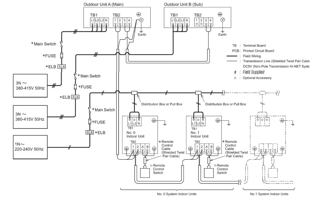
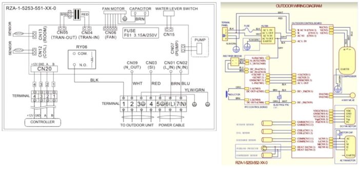
Vrf Wiring Diagram
Troubleshooting
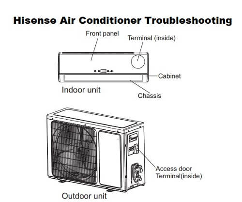
The following cases may not always be a malfunction, please check it before asking for service.
Trouble: Does not run
Analysis:
- If the protector trip or fuse is blown.
- If the plug is not properly plugged.
- If batteries in the remote controller exhausted.
- Please wait for 3 minutes and start again, protector device may be preventing unit to work
Trouble: No cooling or heating air
Analysis:
- Is the air filter dirty?
- Are the intakes and outlets of the air conditioner blocked?
- Is the temperature set properly?
Trouble: Ineffective control
Analysis: If strong interference(from excessive static electricity discharge, power supply voltage abnormality presents, operation will be abnormal. At this time, disconnect from the power supply and connect back 2-3 seconds later.
Trouble: Peculiar odor
Analysis: This odor may come from another source such as furniture, cigarette etc, which is sucked in the unit and blows out with the air.
Electrical Wiring Diagrams
Manuals Pdf
Split Type AC Service Manual PDF
VRF Air Conditioner Manual PDF
Multi-Split Type AC Service Manual
Inverter AC Technical and Service Manual PDF
References
hisense-usa.com/air-products/all-air-products
- Unionaire Air Conditioner Error Codes - December 1, 2025
- Ameristar AC Error Codes and Troubleshooting - December 1, 2025
- Rheem Pool Heat Pump Error Codes - December 1, 2025

my ac hisense is displaying 76
My hisense AC unit cooling is on and off. I can’t find any fault code. I checked condenser board. Ì only found led 1 and led 2 steady light and led 3 continuously blinking. When it ran these three were continuously blinking at same time. I guessed this condition was normal occurrence. Right now, I didn’t have any idea yet.
Can you help me what’s wrong with my unit.
I have a hisense duct type code error 45.
Hi Sige,
45 error: PM fault. There are many reasons for this failure, If you need further analysis, fault code of the driver board is needed by watching the driver board fault led. Analysis can be further to know why and how to operate.
If you have any questions or need further assistance, please let me know. Have a good day.
sir there is showing alarm 01 in Hisense vrf heat pump please explain me what happens
Hisense inverter ac, error 19?
Hi Gomes,
19 error: Suction temperature sensor fault..1.The wiring of the suction temperature sensor connect loose; 2.The suction temperature sensor is failure; 3.The sampling circuit is abnormally.
If you have any questions or need further assistance, please let me know. Have a good day.